
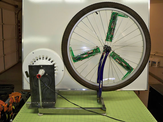
This is a testing rig I constructed for my persistence of vision SpokePOV kit. I used an old bicycle, ceiling fan motor and wiring from an old lamp. It works great as a bench testing rig when programming my SpokePOV boards on the wheel. It could also work as a cheap display device.
You can buy these SpokePOV boards at Adafruit.com and get more details on how to build and use your SpokPOV boards at their sister site ladyada.net
This is the second SpokePOV testing rig I’ve built so this one is being donated(*) to HeatSync Labs for testing, learning, hacking and maybe even as a part-time window display.
(*) Not the SpokePOV boards, just the testing rig and old bicycle wheel.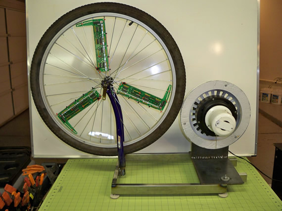
READ —>:
I’m not going to give construction details because it requires a welder, chop saw and plasma torch which most hobbies don’t own. But if you do then you will most likely gleam enough from the photos. In general the lower tube frame is 22 x 13 inches. All the metal is from leftover scraps from older projects so it’s kind of a patchwork quilt design.
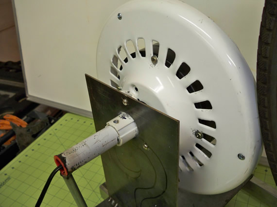
The ceiling fan’s center motor hub, black part, was not large enough to spin the tire fast enough to produce a persistence of vision image in the spokes. So I had to bolt one-half of the fan’s white cowling enclosure to the motor hub which effectively increased the diameter of the motor and greatly increased the rotation speed of the tire. 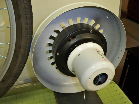
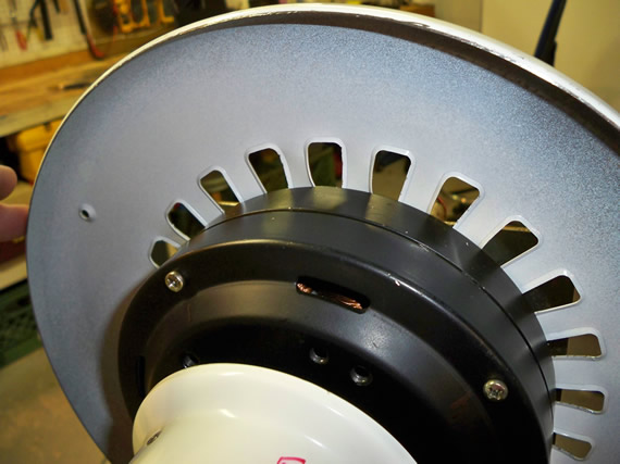
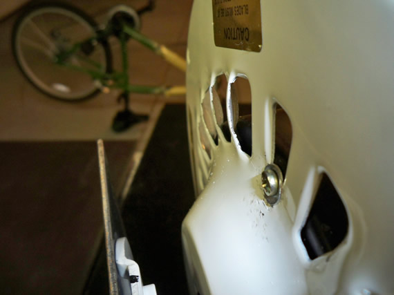
Unfortunately this cowling acted like a speaker amplifying the road noise of the tread on tin. To reduce this I used a cut-off wheel to grind off some of the cowling as you can see in the below photo.
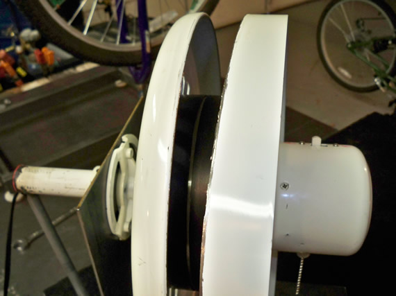
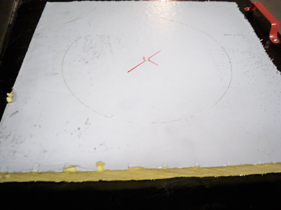
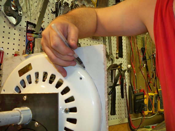
This helped but to further reduce the noise I cutout a circle of high density foam and bolted it inside the cowling. This worked great reducing the road noise to just a low hum. If one were to use this for a display device I would use a tire with little or no tread and it should then be whisper quiet.
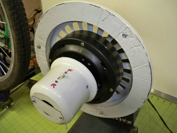
If used as a display device the motor would get a bit hot so I reengineered the vent holes in the cowling by bending them out and backwards by ~35 degrees. This effectively created fan blades and drives air over the motor keeping it cool for continues use.
Below is the mounting bracket for the fan motor using most of the original hardware. The cord is from a discarded floor lamp.
Here are a couple of photos from the left and right ends.
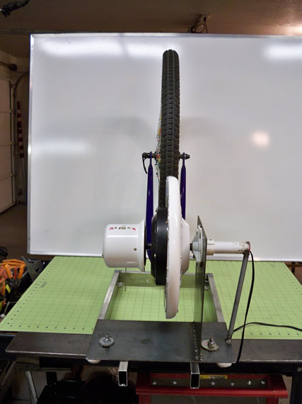
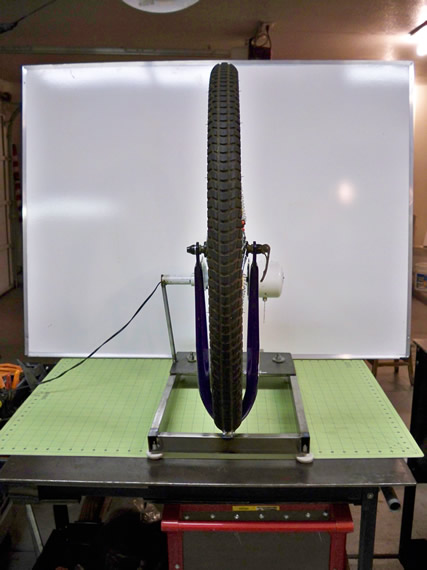
Here you can see I torched out slide notches so the motor mounting can be adjusted forward, backward and a little left and right for different size tires. 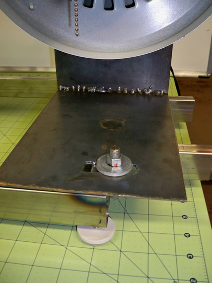
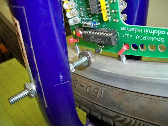
The SpokePOV boards trigger their timing from a Hall Effect sensor on one of the three boards. As this sensor passes under a magnet it sends a signal to all three SpokePOV boards at once so they can calculate the correct LED flash timing based on the tires rotational speed and can then draw a clear persistence of vision image in the spokes.
Here is a photo of a magnet epoxy to the head of a bolt that is run through the bicycle’s upper front fork. In my testing rig the junked-out front bicycle fork is mounted upside-down so the SpokePOV image will be upside-down when viewed but the image will be right-side-up when the tire is on my bicycle.

Links for Beginners in Electronics }:-)
Archives
- April 2017 (1)
- March 2017 (3)
- December 2016 (1)
- November 2016 (3)
- October 2016 (2)
- September 2016 (2)
- August 2016 (4)
- June 2016 (1)
- May 2016 (6)
- April 2016 (1)
- March 2016 (3)
- February 2016 (4)
- January 2016 (3)
- December 2015 (1)
- November 2015 (5)
- September 2015 (1)
- July 2015 (2)
- June 2015 (6)
- March 2015 (1)
- January 2015 (2)
- December 2014 (2)
- November 2014 (4)
- October 2014 (2)
- May 2014 (1)
- March 2014 (5)
- February 2014 (3)
- January 2014 (1)
- September 2013 (2)
- August 2013 (1)
- July 2013 (4)
- June 2013 (3)
- May 2013 (2)
- April 2013 (1)
- March 2013 (3)
- February 2013 (2)
- January 2013 (2)
- December 2012 (1)
- November 2012 (8)
- October 2012 (5)
- September 2012 (1)
- August 2012 (1)
- July 2012 (2)
- May 2012 (2)
- April 2012 (1)
- March 2012 (3)
- February 2012 (2)
- December 2011 (2)
- November 2011 (4)
- October 2011 (1)
- September 2011 (1)
- August 2011 (2)
- May 2011 (2)
- April 2011 (2)
- March 2011 (2)
- February 2011 (2)
- January 2011 (1)
- December 2010 (2)
- November 2010 (2)
- July 2010 (3)
- June 2010 (2)
- April 2010 (1)
- March 2010 (1)
- February 2010 (2)
- January 2010 (1)
- December 2009 (2)
- October 2009 (4)
- March 2009 (1)
- December 2008 (1)
- November 2008 (1)
- August 2008 (1)
- April 2008 (1)
- March 2008 (1)
- February 2008 (1)
- June 2007 (1)
- November 2005 (1)
- April 2005 (1)