Archive for February, 2012
This is a full review of the USB microscope that is sold by Adafruit. It does 20x to 200x and also will let you take measurements if you enter the magnification you are using. I will let the video explain everything but I added some extra photos after the video.
I paid $79,95 for this from Adafruit.com when they first came out months ago. Sorry for the delay but this did give me some time to really get to know all the features. I’m very happy with this USB microscope and have used it quite a lot. In the past I would have to put an eye loupe in front of my camera to take circuit close ups but this microscope does a lot better job. Inspecting very fine details and solder jobs is also tons easier with this microscope.
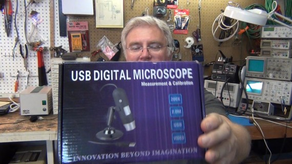
The box:
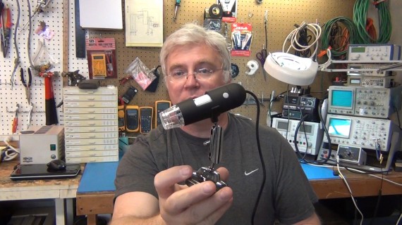
The USB microscope:
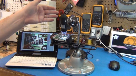
Setup and working:
I wanted to be able to have my circuits in my Panavise when using the USB microscope. I had a flex mic-stand from Radio Shack and some salvaged magnets from some old speakers. I hot glued one large magnet to the top of the mic-stand and another to the bottom of the USB microscope stand. With this setup I can easily switch between the desktop and my mic-stand when I need more flexibility.
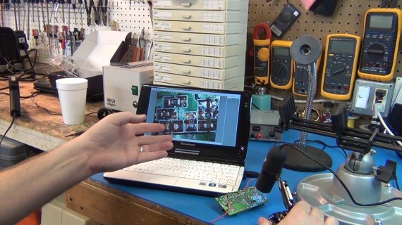
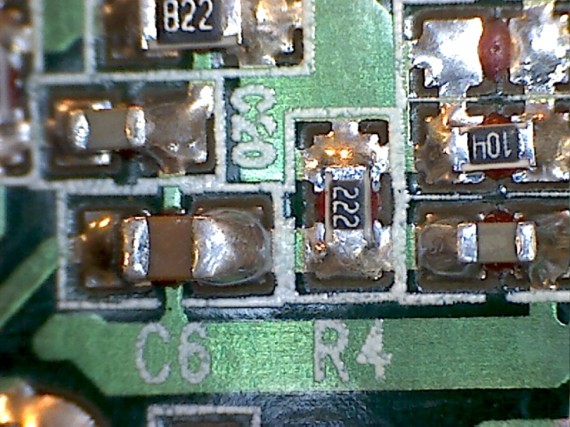
An example of the close up of a (06 x 03) smd resistor using the photo button in the software. REAL NICE!!!
Below is my last example of using the measurement feature included with the software. It worked quite nice but I do wish it had more resolution like 0.001 would have been a better minimum than 0.01 for measuring close ups. This last photo was captured from my video of the laptop screen. I really should have uploaded a real screen shoot from the microscope because that would have look much better, like the one above.
Thanks for joining!
This is Part 6. It is the final installment because I did get the power supply working. You may want to first follow (part1), (part2), (part3), (part4) & (part5).
Somehow I or the crap designed circuit damaged one or more of the chips during part 1.
I started by testing my extra PWM chip (UC3843N) on a bread board. It was a new chip which was never used and it was testing fine until I turned the wrong knob and let out all the magic blue smoke. I took out the PWM chip that was in the control board since part 1 and it tested as bad. In fact Vcc was being shorted to ground. That explained a lot.
I ordered another PWM chips from Digi-Key and after installing it the controller and motor started working. I was having some speed regulation issues which I attributed to not having the heat sinks connected. At that time, which was the end of my video, I assumed the controller was functioning the best it could considering its poor design.
After delivering the motor and controller to HeatSync Labs one of the clever hackers there looked into the speed regulation issue which was not clearing as I thought it would once the heat sinks were mounted. He found another chip on the board that was bad, one of the op-amp chips. It was a chip I too had replaced over a year ago so something was killing the chips on the control board quite easily. This control board was such a pile of crap from day one.
It is working marvelously now so if you’re ever in Mesa Arizona swing by HeatSync Labs and try out their great little mini lathe. Maybe make yourself an aluminum chess piece or two.
Thanks for joining!

