
This is a record of my assembly of the new Sanguino microcontroller board inspired by the Arduino project, specifically the Boarduino version. The sanguino is essentially the big brother to the Arduino and Boarduino (see comparision link). This new board design is the brain child of Zach Hoeken of NY and is distributed through RepRap Research Foundation store.
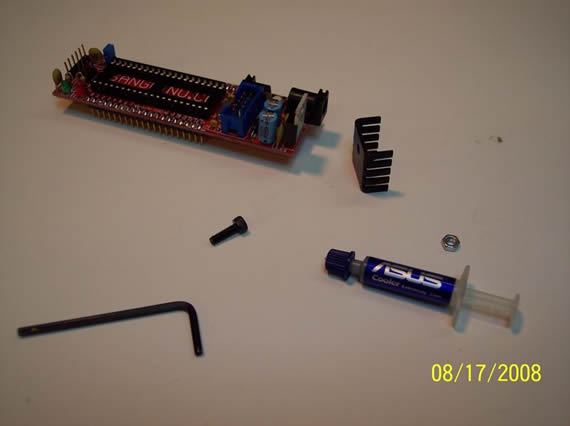
All the parts are accounted for except I got a straight serial header instead of a 90 degree as the docs indicate.
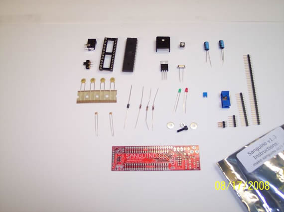
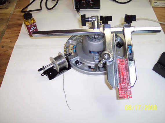
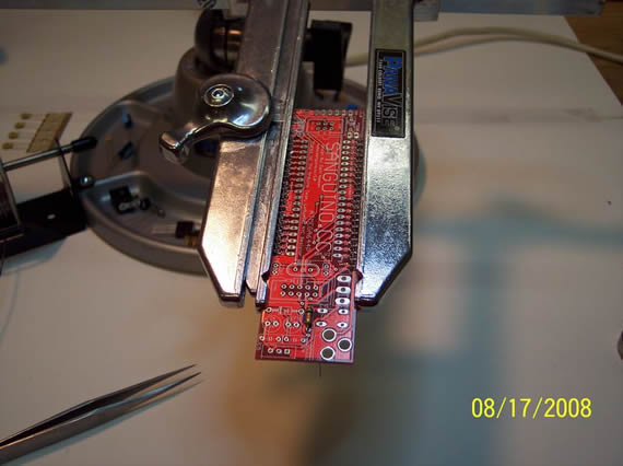
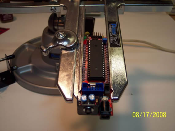
I have the Sanguino in my board vise and all the parts in the vise tray sorted by type. I’m read to go. G33KING out as you can see :)
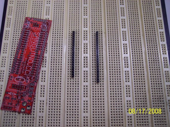
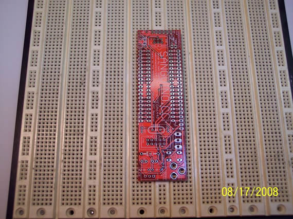
To guarantee that the board pin headers are installed straight I just put them into my breadboard first.
Then I soldered the board in place. The rest of the solder work can be done in the board vise.
Adding 10k resistor
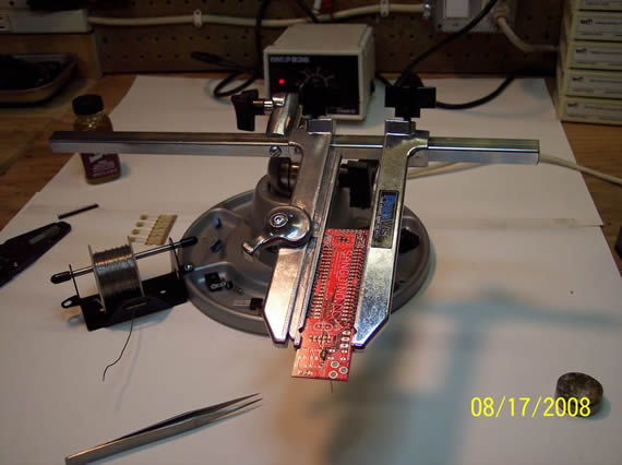
And we’re off
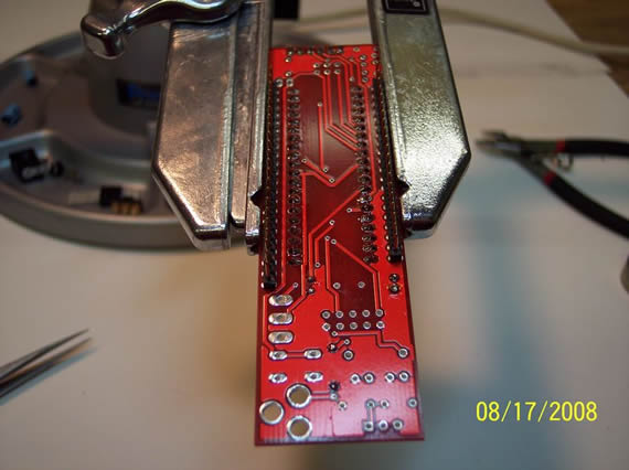
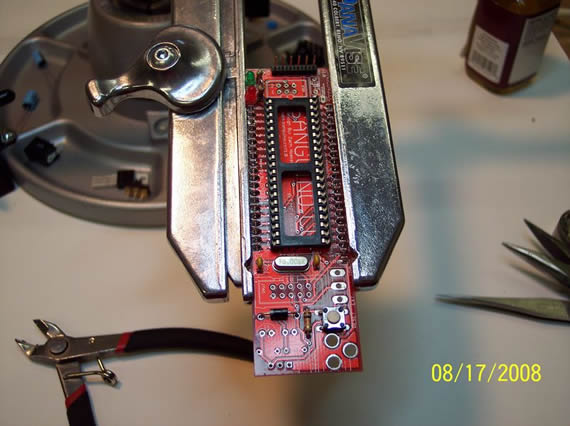
Soldering in the 40-pin DIP socket
Adding the two 33pF capacitors
Now for the diod, two LEDs, 16mhz crystal, two 1k resistors and the reset button.
I used lots of liquid solder flux during the assembly to get nice clean joints. This will clean up easily later.
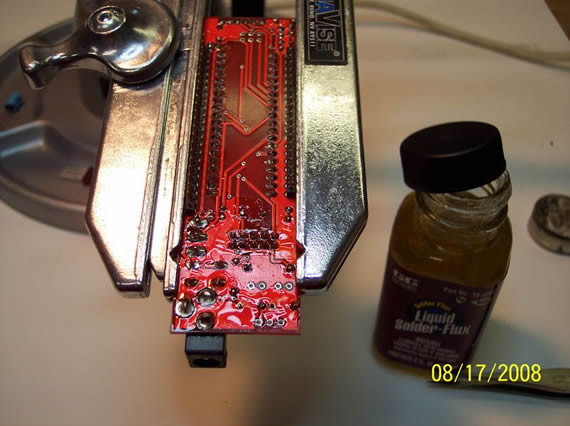
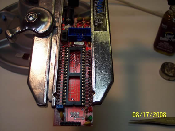
Now for the final parts: just a few more capacitors, headers, power switch, power jack and a 7805 voltage regulator.
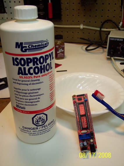
Clean up all that messy flux with 99.953% Isopropyl Alcohol and let dry.
Just to be safe I’m adding the heat sink using some thermal paste.
Make sure to bend the leads in a lot using a flat table top so the chip will pop into the 40-pin DIP socket without damaging the leads. Normally I use both hands to carefully bend the leads in but here I am holding the camera with my right hand.
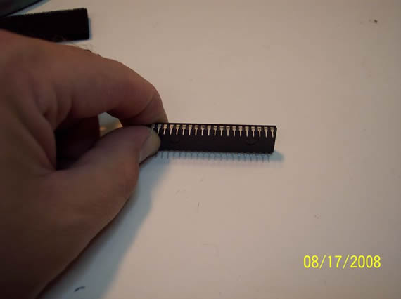
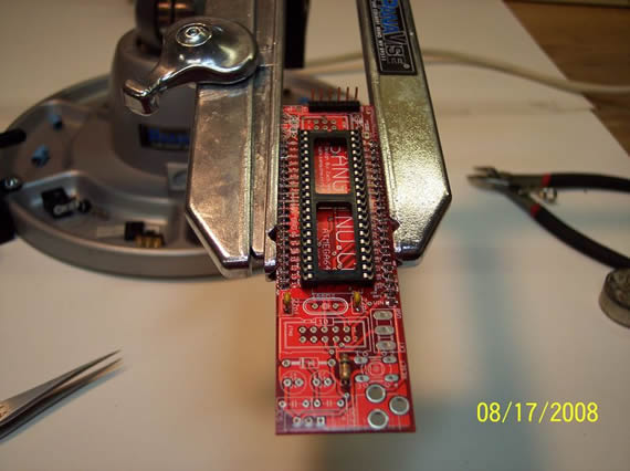
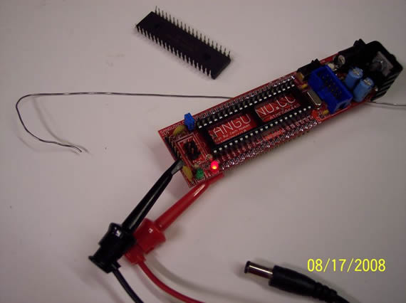
Now insert the awesome Atmel ATmega644p microcontroller chip! (KICK ASS CHIP!!!)
You will need to be very careful when inserting the chip. Look at each pin as you press evenly all around the chips edges. If you see a pin that is going in wrong just backup, straighten it and try again. Also, chips can be put in too high or too low in the socket causing some pins not to connect with the socket connections or be very close to being an open.
Set the power switch to external and plug in a 9vdc wall wart. IT’S ALIVE… (evil laugh)
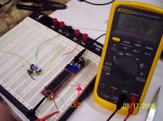
The circuit to the left of the Sanguino is a different project.
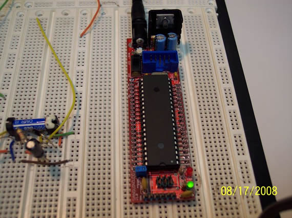
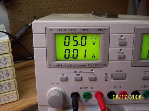
I kind of messed up with my first sketch thinking that the onboard red LED was connected to digital out 13 like on the Arduino. Being I did not see the red onboard debug LED flashing after loading my first sketch I though maybe my chip was bad or my LED was not soldered in correctly. I setup a 5v supply for testing the red debug LED in the circuit.
I took out the chip and connected the 5v from pin 1 to ground and as you see the red debug LED and wiring are just fine. Of course this is when I realized I was working with an all new form factor of the Arduino and needed to adjust my sketches accordantly. I knew this all along, but I was just so excited to see it running I skipped that step.
I then put the chip back in and successfully loaded several “updated” sketches without a problem. All worked just fine. Here you see the infamous BLINK sketch to the right of the Sanguino board (red LED on the breadboard). The circuit to the left of the Sanguino is a different project. Tomorrow I’m connecting servos BABY! (Bigger evil laugh…)

Links for Beginners in Electronics }:-)
Archives
- April 2017 (1)
- March 2017 (3)
- December 2016 (1)
- November 2016 (3)
- October 2016 (2)
- September 2016 (2)
- August 2016 (4)
- June 2016 (1)
- May 2016 (6)
- April 2016 (1)
- March 2016 (3)
- February 2016 (4)
- January 2016 (3)
- December 2015 (1)
- November 2015 (5)
- September 2015 (1)
- July 2015 (2)
- June 2015 (6)
- March 2015 (1)
- January 2015 (2)
- December 2014 (2)
- November 2014 (4)
- October 2014 (2)
- May 2014 (1)
- March 2014 (5)
- February 2014 (3)
- January 2014 (1)
- September 2013 (2)
- August 2013 (1)
- July 2013 (4)
- June 2013 (3)
- May 2013 (2)
- April 2013 (1)
- March 2013 (3)
- February 2013 (2)
- January 2013 (2)
- December 2012 (1)
- November 2012 (8)
- October 2012 (5)
- September 2012 (1)
- August 2012 (1)
- July 2012 (2)
- May 2012 (2)
- April 2012 (1)
- March 2012 (3)
- February 2012 (2)
- December 2011 (2)
- November 2011 (4)
- October 2011 (1)
- September 2011 (1)
- August 2011 (2)
- May 2011 (2)
- April 2011 (2)
- March 2011 (2)
- February 2011 (2)
- January 2011 (1)
- December 2010 (2)
- November 2010 (2)
- July 2010 (3)
- June 2010 (2)
- April 2010 (1)
- March 2010 (1)
- February 2010 (2)
- January 2010 (1)
- December 2009 (2)
- October 2009 (4)
- March 2009 (1)
- December 2008 (1)
- November 2008 (1)
- August 2008 (1)
- April 2008 (1)
- March 2008 (1)
- February 2008 (1)
- June 2007 (1)
- November 2005 (1)
- April 2005 (1)