
This is my honking pumpkin project to scare Trick-Or-Treaters. The little monsters will not be able to resisted pressing the red button on the pumpkins nose which will trigger the eyes to glow for a second and just when they think that’s it a set of 105 decibel car horns hidden in the pumpkin will blast and send them running.
For the most part my plan worked on Halloween 2008 but I built it fast and with some cheap parts. What follows is documentation of my re-build to remove some heinous false triggering and general improvements. Enjoy the below videos and photos.
Parts list is at the very bottom and here is a link to the circuit: –>circuit
Special thanks go to my inspiration for this project by an original design posted by Marc de Vinck Oct 28, 2008 at blog.makezine.com
UPDATE 10/15/2009: Installed BIG RED button which is much more tempting don’t you think?
Cutting out hole for new nose button.

The new nose is ready!

False secondary triggering of my Honking Pumkin.
Short honk setting without false triggering
Describing false trigger problem
Showing false triggers on Oscilloscope
You can see the horns in the mouth and that red button sure is tempting!

Photo just after pressing button showing the 12v incandescent lights running in the eyes of the pumpkin. These don’t draw much amps and are turned on by just a MOSFET for the time delay set by the 1st 555 timer.
The internal wiring guts of the honking pumpkin project. I twisted all the lines and made them long enough to be used in most anything if it’s not Halloween. Here you see the 5Ah battery from Radio Shack which powers everything, large relay for operating the two horns, Power on/off switch, two red bulbs, red button and an ALTOIDS tin which houses the control board. The large battery is required because of the 4.5 amps that the car horns need.
This is the 5Ah 12v battery from Radio Shack. If you get it online at Radio Shack it’s only $15 and you can save the shipping charges by having it delivered to a local Radio Shack. The 12v-40amp relay came free with the two horns in a kit from Harbor Freight #99911 for $9. Later you will see some scope traces that show a ton of noise that was causing false triggering. The culprit was this cheap relay that came with the horns.
Below is a photo of just the crap relay.
Here is a close up of the relay where it is clearly marked 12v 40amps which is just what you need for automotive relays. But wait until you see what cheap shenanigans these Chinese are pulling when you open it up and take a look inside!
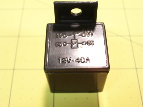
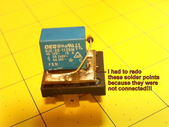
What is inside is just a cheap PC board low range relay. Nothing close to a 12v-40amp automotive relay. This part is rated for 12 volts DC but the data sheet for this relay states: 3-10 amps miniature PC Board Relay. The exact version of this part I got is only rated at 150W. This means at 12 volts DC you can’t exceed 12.5amp which is a long way from 40A and I personally wouldn’t push it past half its maximin. On top of all that my part is marked “12DM” which means its contacts can only switching power up to 5amps at 12v. The part number is OJE-SS-112DM and here is a link to the data sheet.
This was the piece of junk causing all my false trigger problems and as noted in this photo I had to take it apart and solder the pads to the relay because they did such a crap job making this cheat that the relay wasn’t even soldered down completely.
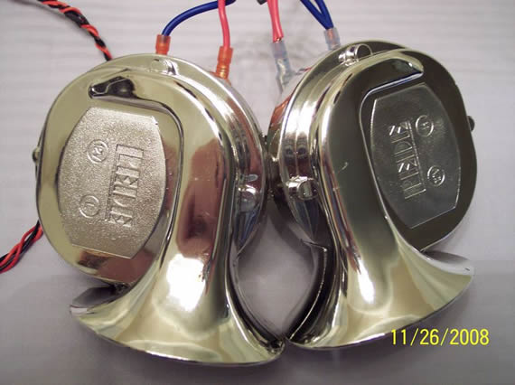
Dual horns from Harbor Freight # 99911 for $9. One is high pitch and the other is low. They put out a blasting 105 decibels!
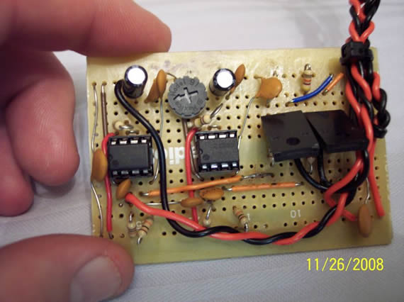
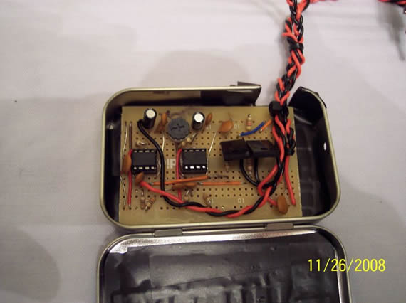
Control board showing the two 555 timers, two MOSFETs, pot to control horn blast timing and other discrete elements. The first 555 timer starts when the red button is pushed and it turns on the red 12v bulbs through the 1st MOSFET (P10NK60ZFP). After 1 second this timer stops and cascades a pulse to the 2nd 555 timer which repeats the process turning on the horns through the 2nd MOSFET and relay. You could use a 556 chip to simplify the circuit because a 556 has two 555s built in. The two .1uf capacitors across the power leads on both ends of the board and the two .01uf capacitors routed from the 555 trigger pins to ground are very important to filter stray noise from the horns and long wires. Without these extra capacitors false triggering is extremely prevalent.
Control circuit in ALTOIDS tin with a small snip of the side cut away. I also put down about 4 layers of electrical tap on the button of the tin and cut sides to prevent cuts and shorts circuits.
I just pressed the button and the first 555 timer is running keeping the red bulbs on for 1 second. This makes the user think that is all that will be going on, but after that 1 second they will get a 105 decibel blast just when they don’t expect it. The horn blast can be controlled from 1.5 seconds down to a quick beep just incase you don’t want kids to wet themselves.

My new Tektronix 2012B with a testing waveform board hooked up. This was a ton of help tracing down noise causing false trigging in my pumpkin control circuit as I will document next. This is actually a Christmas gift that I’m not supposed to get for another month but I had to test it before letting it be rapped up for Christmas right? :)

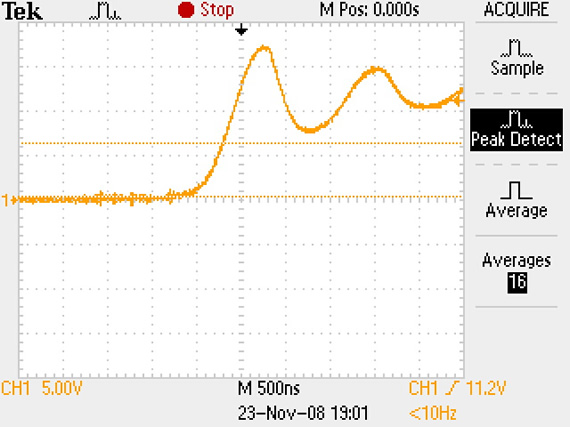
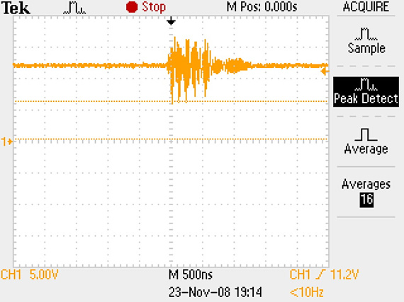
This shows the waveform on the trigger pin to the first 555 timer. This large wave is noise from the long battery wires and was causing false triggering of the timers when the power switch was turned on. After adding a 0.1uf capacitor across the power terminals of the control board this waveform flattened out and I no longer had false power-on triggering.
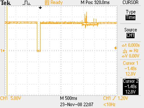
The first pulse from 12v to ground was the button press at the trigger pin of the 1st 555 timer. The spikes farther down are from noise on the power lines caused by the faulty relay as noted earlier. These spikes where so bad they frequently gave false triggering of the 1st 555 timer and caused the pumpkin to never stop flashing and honking, very annoying.
I was trying to find out what was causing the annoying false triggers and this trace shows a lot of noise at the trigger pin of the 1st 555 timer just as the horn is blasting. This trace did not cause a false trigger because it was not that bad.
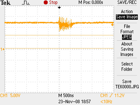
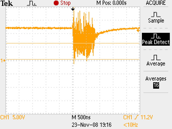
This is the same probe point as the last photo but the noise this time was enough to cause a false trigger. It took me some time to trace this noise down to the cheap relay that came with the horns. (made in China, go figure)
Same probe point again but I still didn’t know about the bad relay and I was trying different capacitors at different points trying to filter out the noise. Here I made the problem worse and the cap had to just charge up again after the nosier.
The first long pulse is the on pulse to the 1st MOSFET that controls the lights and the spikes after the lights turn off is that horrible noise on the line from the horn being operated by the junk relay.
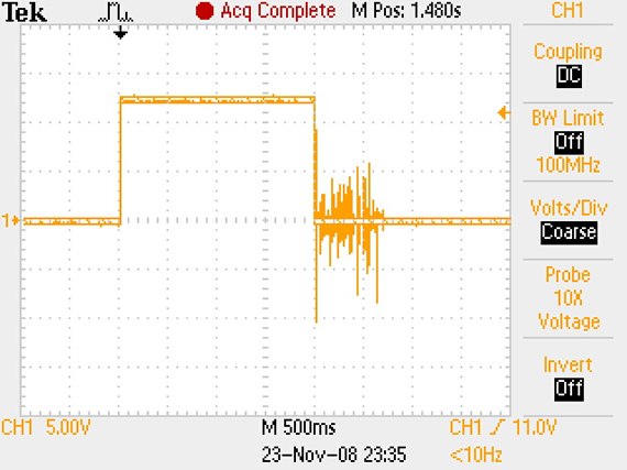
This is a waveform of the pulse that turns on the 2nd MOSFET and Relay combo that operate the horns. Once again you can see all that noise that was causing the endless false triggering.
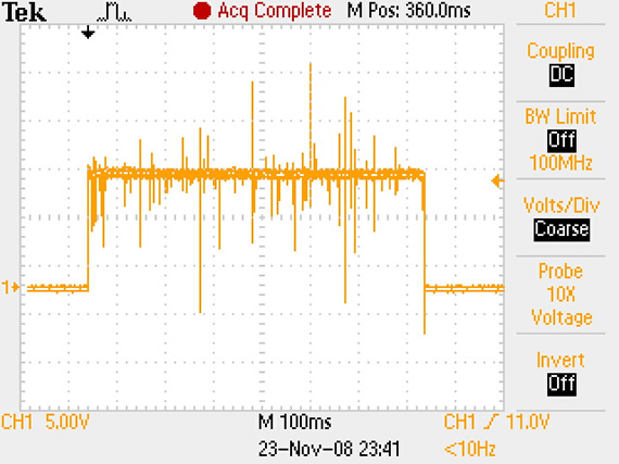
Here the scope probe is on the power lines to the control board showing 12V but I fired the horn by jumpering to the 2nd MOSFET that operates the relay. Doing this I was able to skip the timers all together but you can still see all the feedback noise. 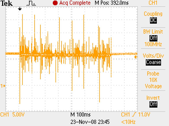
The probe is still on the power lines of control board and I jumper the horn directly from the battery which bypassed all the control circuitry. Still getting noise to my control board, darn! But not as much noise now which lead me to start questioning the relay itself. 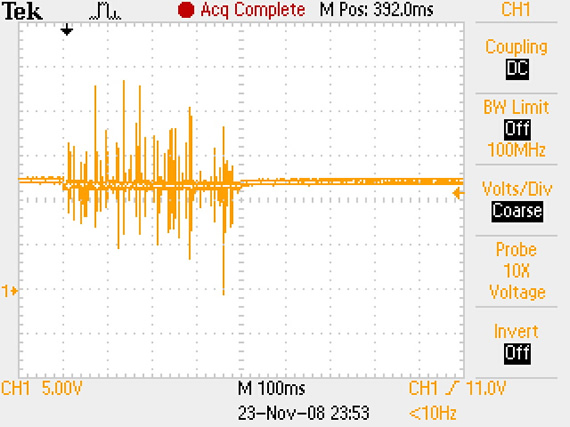
Finally, the signal is clean. I took apart the relay (made in China) and found a cheap 5A relay inside. The outer case of the relay was marked 12v 40A but the inside was clearly the cheapest crap relay they could use and it was not even soldered to the spade leads at two points which was causing intermittent connections and tons of line noise. This was the cause of my line noise and false triggering. Thank God for a good Tektronix scope, I’m not sure I could have traced this down without it. ![]()
Below is a parts, materials and tools list for this project.
Where possible I included pricing and a link to a retailer.
======================================
Tools:
———————————————————–
(1) Solder iron
(1) Digital Multi Meter
(1) Knife to cut eyes, mouth and top out of the polyvinyl pumpkin
(1) Wire cutters
(1) Wire strippers
(1) Exacto Knife
(1) De-solder bride or a solder sucker to correct mistakes
(1) Crimp tool for terminal connectors
(1) 9v battery or power supply for testing your control circuit,
but once you start turning on the horn you will
need to use the 5Ah 12v battery because the horns take 4.5A.
You could do all your prototyping and testing with the 12v
5Ah battery but if you make a short you will get quite a lot of sparks and smoke.
So if you do all your testing with the 9v battery or
current limited power supply they are a lot more forgiving.
General supplies:
———————————————————–
(1) Solder
(1) Shrink rap good for 18AWG and 22AWG stranded wire.
(1) Wire ties
Parts:
———————————————————–
Ceramic disk capacitors
(6) 0.01uf
(2) 0.05uf
(2) 0.1uf
Electrolytic capacitors
(2) 1uf rated for 50v
Resistors
(6) 10K
(2) 47K
(1) 100K
(1) 500K POT
(1) 1.5M
(1) ALTOIDS tin
(1) Pumpkin: AKA FunKin
14.5 inch Polyvinyl (foam)
Michaels craft and art store. Can’t buy online at Michaels but they are cheap at the stores.
You can buy online at: Pottery Barn kids or The Funkin Patch.
(2) MOSFET STMicroelectronics – P10NK60ZFP
N-channel 650 V, 0.65ohm, 10 A, SuperMESH Power MOSFET Zener-protected
Get a free samples at: Samples P10NK60ZFP Buy for $2.69 at: digikey.com P10NK60ZFP Datasheet
(1) Solderless Breadboard Jumper Wire Kit
#276-173 $5.99 Jumper Wire Kit
(1) 75-Ft. UL-Recognized Hookup Wire (22AWG) stranded
#278-1224 $6.59 (Includes three 25ft spools of black, green, red) 22AWG spools in black, green, red
(1) 45-Ft. UL-Recognized Hookup Wire (18AWG) stranded
#278-1226 $6.99 (Includes three 15ft spool of black, green, red) 18AWG spools in black, green, red
(1) 1/4″ Fully Insulated Quick Disconnect Spade Connectors (10-Pack)
#64-3131 $2.19 Disconnects
(1) Battery 12V/5Ah NP5-12 Sealed Lead-Acid
#55029979 $29.99 (I used this but I had it already) Battery 12V/5Ah
or 12V/1.3Ah Sealed Lead Acid Battery $15.99 Battery 12V/1.3Ah
(1) Toggle Switch with On/Off Label Plate
#275-602 $2.99 On/Off Switch (1) Mini SPDT 3-Amp Momentary Pushbutton Switch
#275-1549 $3.99 (I used this because I already had it) Momentary Switch small
#COM-09336 $1.95 (MUCH better button !!!!) Momentary Switch large
(1) Matching Printed Circuit Board with 550 Connect Points
This project board has the same layout as a breadboard so
transferring your circuit to a final board is easy.
#276-170 $2.99 Project Circuit Board
(1) Modular IC Breadboard Socket
This is not needed but if you don’t have a prototyping breadboard you should get this one
so you can layout and test your circuit before soldering all your electronics permanently.
#276-003 $8.99 Breadboard
(2) TLC555/TLC555CP LinCMOS Timer (8-Pin DIP)
#276-1718 $1.69 555 IC (2) 8-Pin Retention sockets
You need these for the 555 timers because if you kill one it’s a ton easier to
replace if they are in a socket instead of soldered to the project board.
#276-1995 $0.48 8-Pin Sockets
(1 package) Red Sylvania / Bulb – Instrument Panel Light (set of two bulbs)
#194R $2.99 from Autozone.com but you can get any 12v red buld you like.
(1) BATTERY CHARGER 12v 1.5 AMP
#93258-1VGA $15.00 BATTERY CHARGER
(1) Horn Set 12 Volt (comes with two horns for high and low plus a relay to control the horns)
#99911 $9.00 (in store only!) 12 Volt horn set

Links for Beginners in Electronics }:-)
Archives
- April 2017 (1)
- March 2017 (3)
- December 2016 (1)
- November 2016 (3)
- October 2016 (2)
- September 2016 (2)
- August 2016 (4)
- June 2016 (1)
- May 2016 (6)
- April 2016 (1)
- March 2016 (3)
- February 2016 (4)
- January 2016 (3)
- December 2015 (1)
- November 2015 (5)
- September 2015 (1)
- July 2015 (2)
- June 2015 (6)
- March 2015 (1)
- January 2015 (2)
- December 2014 (2)
- November 2014 (4)
- October 2014 (2)
- May 2014 (1)
- March 2014 (5)
- February 2014 (3)
- January 2014 (1)
- September 2013 (2)
- August 2013 (1)
- July 2013 (4)
- June 2013 (3)
- May 2013 (2)
- April 2013 (1)
- March 2013 (3)
- February 2013 (2)
- January 2013 (2)
- December 2012 (1)
- November 2012 (8)
- October 2012 (5)
- September 2012 (1)
- August 2012 (1)
- July 2012 (2)
- May 2012 (2)
- April 2012 (1)
- March 2012 (3)
- February 2012 (2)
- December 2011 (2)
- November 2011 (4)
- October 2011 (1)
- September 2011 (1)
- August 2011 (2)
- May 2011 (2)
- April 2011 (2)
- March 2011 (2)
- February 2011 (2)
- January 2011 (1)
- December 2010 (2)
- November 2010 (2)
- July 2010 (3)
- June 2010 (2)
- April 2010 (1)
- March 2010 (1)
- February 2010 (2)
- January 2010 (1)
- December 2009 (2)
- October 2009 (4)
- March 2009 (1)
- December 2008 (1)
- November 2008 (1)
- August 2008 (1)
- April 2008 (1)
- March 2008 (1)
- February 2008 (1)
- June 2007 (1)
- November 2005 (1)
- April 2005 (1)