
I have a custom Arduino board project to share including bonus steps at the end on how to program a blank ATmega168 or ATmega328 with your Arduino sketch directly from the Arduino IDE environment using an USBTinyISP programmer from Adafruit.

I’m going to hack a Christmas photo frame I got a few years back when my son visited Santa Clause. The photo of him sitting on Santa’s knee came with a nice frame that had 5 LEDs that flashed when you turned it on. It ran on two AAs and used a “chip-on-board” to control the flashing pattern of the LEDs.
The problem was that this thing flashed all 5 LEDs four times a second! We could never leave it on because it would drive you nuts. Ever since I purchased it I have wanted to hack it so the lighting was not so annoying. This is going to be mostly a video posting but I will put in some “how to” notes, helpful links, photos, circuit and code so it will be more useful to you for adding such a hack to a project of your own.
Below is a video of me describing the problem and proposing the project. A few things did change after the video but I will note the changes below.
Below is the original board from the photo frame. The “chip-on-board” is under the black blob.
READ —>:
This “chip-on-board” is also called glob-top or blob-top. The chip “die” is glued to the PCB and wires are bonded from it to the PCB pads direclty on the board. I first tested the “chip-on-board” to see if I could change it in any way to flash slower.

Altering the original board would have saved me a lot of development time but wouldn’t have been as cool or customizable so I’m glade now that I couldn’t change it.
One of the first things I had to do was map out all the wires going to the different LEDs for later reference when wiring up my custom control board.

The original board ran on 3v and put out a controlled voltage pulse to each LED 4 times a second so no inline resistors were needed. My circuit would be pushing 5v on the output pins and would need current limiting inline resistors. Below I’m testing the max current I wanted to run through the green LED on the Christmas tree. I had my Multimeter connected in series reading current values (not seen in this photo).

The different colored LEDs turn on at slightly different current values. Below is a photo of my calculations for the different series resistors needed for each colored LED to get the exact current I wanted from the 5v ATmega chip.

Yes, that was a bit too anal. I ended up just using the calculations to pick standard resistor values close to each calculated value (220 ohm). In the end I could have even picked higher values for the resistors because the LEDs ran at ~13mA each and were too bright in a dark room. I might change the resistor values next year. Unfortunately I soldered the resistors inline with the wires going to the LEDs and protected them with heat shrink so changing them will not be easy.
Next I whacked out some code into an Arduino Duemilanove and tested the code on a breadboard mockup.

Here is a video of it running the test code. Later I had to change the code in the final project board but you will see the reason later.
I changed my plan from an Atmel ATmeta328 to a cheaper ATmeta168. The code and pin-outs didn’t have to change at all because these chips are identical except for memory size. I didn’t need the extra code space of the larger chip and I had extra blank ATmega168s anyway.
I’m not going to use the Arduino bootloader so I’m using blank Atmeg chips I bought from Digikey. I had planed on popping out the ATmega chip from the final project board socket and putting it in my Arduino Duemilanove and using it’s 6 pin ICSP (In Circuit Serial Programmer) header with a USBTinyISP in circuit programmer every time I wanted to change the code, but as you can see in the below photo I decided to add the 6 pin ICSP heater to my final custom Arduino project board. This is better because with just a few extra wires I can reprogram the ATmega in place. There are a few tricks if you want to do the programming directly from the Arduino IDE which I will cover at the end.

Bottom photo of custom Arduino board:

Warning: Don’t design a circuit that uses any of the ATmega’s 6 ICSP pins. If you do then you my not be able to program the chip in circuit. This did happen to me with this project so I had to change my design by switching one of the PWM pins which was also used by the ICSP header to a non-PWN digital pin. I also had to change my code from using PWM to just “on/off” for the LED that had to be switched to the alternate pin.
The next issue to tackle is the power source. I could have run this off a 9v battery but then I would have had to design in a 5v regulator. Instead I dug through my junk box and found an old Linksys network HUB that ran on 5v and had a nice clean 5v switching power supply wall wart. I wanting to keep things simple so I just cut the 5v barrel plug from the PCB including some traces and a few surface mount filter caps on the under side.

I use a tin snips to cut PCB board like this. Nice and clean and much faster then unsoldering and re-soldering everything to a new board.

I cut an access whole in the back of the photo frame for the 5v barrel plug.

Then I hot glued the barrel plug on the inside after tapping off a couple of supply wires for the custom Arduino board.

And here is the video of the final project working.
Here is my code:
/*
** Christmas photo frame lighting MOD
** By: Todd Harrison
** Date: 12/15/2010
** Details at: http://www.toddfun.com
*/

int tree_ledPin = 2;    //Digital pin 2 on the Arduino Duemilanove which maps to pin 4 on ATmega168 chip.
int top_ledPin = 3;     //Digital pin 3 on the Arduino Duemilanove which maps to pin 5 on ATmega168 chip.
int lamp3_ledPin = 4;   //Digital pin 4 on the Arduino Duemilanove which maps to pin 6 on ATmega168 chip.
int lamp1_ledPin = 9;   //Digital pin 9  with (PWM) on the Arduino Duemilanove which maps to pin 15 on ATmega168 chip.
int lamp2_ledPin = 10;  //Digital pin 10 with (PWM) on the Arduino Duemilanove which maps to pin 16 on ATmega168 chip.

void setup(){
	pinMode(lamp1_ledPin, OUTPUT);
	pinMode(lamp2_ledPin, OUTPUT);
	pinMode(lamp3_ledPin, OUTPUT);
	pinMode(top_ledPin, OUTPUT);
	pinMode(tree_ledPin, OUTPUT);
}

void loop(){
	for (int i=0; i <= 255; i++){
	  analogWrite(lamp1_ledPin,i);
	  delay(20);
	}

	for (int i=0; i <= 255; i++){
	  analogWrite(lamp2_ledPin,i);
	  delay(20);
	}

	for (int i=0; i<=3; i++){
	  digitalWrite(lamp3_ledPin,HIGH);
	  delay(500);

	  digitalWrite(top_ledPin,HIGH);
	  delay(500);

	  digitalWrite(tree_ledPin,HIGH);
	  delay(500);

	  digitalWrite(tree_ledPin,LOW);
	  delay(500);

	  digitalWrite(top_ledPin,LOW);
	  delay(500);

	  digitalWrite(lamp3_ledPin,LOW);
	  delay(500);

	  analogWrite(lamp2_ledPin,0);
	  delay(500);

	  analogWrite(lamp2_ledPin,255);
	  delay(500);

	}

	for (int i=255; i >= 0; i--){
	  analogWrite(lamp2_ledPin,i);
	  delay(20);
	}

	for (int i=255; i >= 0; i--){
	  analogWrite(lamp1_ledPin,i);
	  delay(20);
	}

	delay(2000);
}
Below is my circuit drawing (click to see larger image). I could have simplified my circuit by eliminating the ICSP header. If I did I would have needed to program the chip in the Arduino Duemilanove board using its ICSP header and then transfer it to my final circuit board. I chose to add the header so I could more easily change the code without removing the chip.

As promised here is how I use the Arduino IDE and USBTinyISP to program a blank ATmega chip. Close the Arduino IDE if you have it currently running.
We are going to use the Arduino IDE to write our program to our ATmega chip but we are not using a bootloader. The Arduino IDE 0022 does support this process but we first must setup our own board definition. Yes, we could use avrdude.exe at the command line to load our program but I find using the IDE a lot cleaner being you can code and upload from within the same tool using this trick.
First you need to know how you want your ATmega chip fuses set in order to correctly configure your blank chip. If you don’t know anything about chip fuses read up on it at Ladyada.com. Then go to this site: AVR Fuse Calculator and pick your AVR chip you’re using. I was using a blank atmega168.
There are three ways to enter what chip configurations you want on this page.
- Feature configuration
- Manual fuse bits configuration
- Current settings
Making changes to any one of these three will change the other two. The third section “Current settings” is where you will see your required fuse settings for the chip features you pick.
When programming blank atmega168 or atmega328 as found in many Arduino boards you will have 3 fuses to set.
- Low fuse
- High fuse
- Extended fuse
You may have to read the data sheet for your chip to know what features you want in order to set the fuses but for this project I wanted the main feature drop down selection set to:
Int. RC Osc. 8MHz; Start-up time PWRDWN/RESET: 6 CK/14 CK + 65 ms; [CKSEL=0010 SUT=10]; default value
This means I will be running on the internal Atmega chip RC oscillator, which means no external crystal or resonator and at 8MHz. Don’t check the divided by 8. Set the brown out to 2.7v. Check the SPI enabled box. I’m not using the Arduino boot loader for this project so check the Boot Reset vector Enabled (default address=$0000).
When you apply these feature settings for the ATmega168p chip you will get:
- Low fuse: 0xE2
- High fuse: 0xDD
- Extended fuse: 0xF8 (However, If you read the notes you will want to use 0x00)
If you would rather use an ATmega328p in the same configuration your fuses would be:
- Low fuse: 0xE2
- High fuse: 0xD8
- Extended fuse: 0xFD (However, If you read the notes you will want to use 0x05)
Of course these are my personal chooses when using an ATmega168 on internal RC oscillator. If your project needs very precise timing for SPI or I^2C or something else you will have to wire up a crystal and change your fuse options to match.
You now need to create a board definition for your new custom Arduino board before you can program it directly from the Arduino IDE. On your PC navigate to your Arduino IDE “boards.txt” file. This was my path:
- My Documents\Electronics\Arduino\arduino-0022\hardware\arduino\boards.txt
Edit this file when Arduino IDE is not running. To make this step simple just create a copy of the existing board definition section for:
- diecimila.name=Arduino Diecimila, Duemilanove, or Nano w/ ATmega168
However if you are using an ATmega328 chip then make a copy of the existing board definition section for:
- atmega328.name=Arduino Duemilanove or Nano w/ ATmega328
Change all the prefix names for your coped section from “diecimila” to the name you are giving your custom board. I picked “custom_board.”.
Change the “custom_board.name=” description to something descriptive and to your liking. Later when you start the Arduino IDE this new named board will be listed in the board choices. I used “Todd’s custom board w/ ATmega168 8MHz internal RC clock.”
You have to add “.upload.using=usbtinyisp” but if you’re not using the USBTinyISP program you can get the list of other programmers from the programmers.txt file in the same folder. I did find that his processes is case and space sensitive so remove any spaces and use only lower case when typing the programmer name in your boards definition file here.
Change the fuse settings using what you calculated above.
Remove the “.bootloader.path=” line
Remove the “.bootloader.file=” line
Last but not least change your chip frequency to 8MHz “.build.f_cpu=8000000L”.
Don’t change any other settings.
Here is my new custom Arduino board definition section:
##############################################################
custom_board.name=Todd’s custom board w/ ATmega168 8MHz internal RC clock.
custom_board.upload.protocol=stk500
custom_board.upload.maximum_size=16384
custom_board.upload.speed=19200
custom_board.upload.using=usbtinyisp
custom_board.bootloader.low_fuses=0xE2
custom_board.bootloader.high_fuses=0xDD
custom_board.bootloader.extended_fuses=0x00
custom_board.bootloader.unlock_bits=0x3F
custom_board.bootloader.lock_bits=0x0F
custom_board.build.mcu=atmega168
custom_board.build.f_cpu=8000000L
custom_board.build.core=Arduino
##############################################################
Save the boards.txt file when you’re done.
If you’re to the point where you are trying to create your own custom Arduino boards I will assume you know how to use the Arduino IDE. If not, STOP go to http://www.arduino.cc/ and start from the beginning. Sorry, this is not an Arduino IDE tutorial.
You will need an in-circuit serial programmer like the USBTinyISP or AVRISP mkII. Yes you can use a home built parallel port programming cable. But to keep things simple I’m only going to cover using the USBTinyISP.
Connect your USBTinyISP to your board *correctly* and set its jumper to power the board. If you don’t want the USBTinyISP to power your board then remove the jumper on the USBTinyISP and power your board from an external 5v supply. Connect the USBTinyISP to your computer.
Now you can start the Arduino IDE. I’m currently using Arduino IDE build-0022.
From the menu pick “Tools >> Boards >> YOUR BOARD”. For me I picked my custom board “Todd’s custom board w/ ATmega168 8MHz internal RC clock.” which is what we added to the boards.txt file as noted above.
Open your current sketch project or start typing new code. When you’re done coding save your sketch and then click the “Upload” button. If your sketch passed the compile process it will create your HEX file and upload it to your chip incluidng setting the fuses as configured in the boards.txt file for your board.
Once your HEX file is written to your chip it will immediately start running your program. You may have to disconnect your programmer before things work if any ICSP pins are used for other circuit connections. Every time the circuit is powered on your program will start immediately. If you want to change the code just repeat the programming process above.
This was a minimal “bare-bones” custom Arudino board so if you want your custom Arduino board to be closer to the full functionality of an Arduino Duemilanove or UNO then checkout these great sites:
- http://itp.nyu.edu/physcomp/Tutorials/ArduinoBreadboard
- http://www.ladyada.net/learn/avr/programming.html
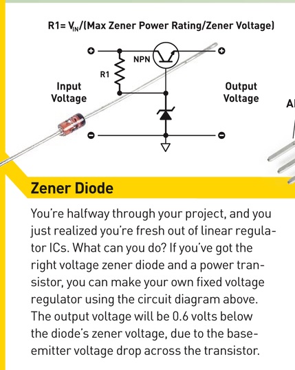
Not related to this project directly but below is a nice zener diode reg circuit you can build in a pinch. This photo is from Make Magazine Volume 47 p.51

Links for Beginners in Electronics }:-)
Archives
- April 2017 (1)
- March 2017 (3)
- December 2016 (1)
- November 2016 (3)
- October 2016 (2)
- September 2016 (2)
- August 2016 (4)
- June 2016 (1)
- May 2016 (6)
- April 2016 (1)
- March 2016 (3)
- February 2016 (4)
- January 2016 (3)
- December 2015 (1)
- November 2015 (5)
- September 2015 (1)
- July 2015 (2)
- June 2015 (6)
- March 2015 (1)
- January 2015 (2)
- December 2014 (2)
- November 2014 (4)
- October 2014 (2)
- May 2014 (1)
- March 2014 (5)
- February 2014 (3)
- January 2014 (1)
- September 2013 (2)
- August 2013 (1)
- July 2013 (4)
- June 2013 (3)
- May 2013 (2)
- April 2013 (1)
- March 2013 (3)
- February 2013 (2)
- January 2013 (2)
- December 2012 (1)
- November 2012 (8)
- October 2012 (5)
- September 2012 (1)
- August 2012 (1)
- July 2012 (2)
- May 2012 (2)
- April 2012 (1)
- March 2012 (3)
- February 2012 (2)
- December 2011 (2)
- November 2011 (4)
- October 2011 (1)
- September 2011 (1)
- August 2011 (2)
- May 2011 (2)
- April 2011 (2)
- March 2011 (2)
- February 2011 (2)
- January 2011 (1)
- December 2010 (2)
- November 2010 (2)
- July 2010 (3)
- June 2010 (2)
- April 2010 (1)
- March 2010 (1)
- February 2010 (2)
- January 2010 (1)
- December 2009 (2)
- October 2009 (4)
- March 2009 (1)
- December 2008 (1)
- November 2008 (1)
- August 2008 (1)
- April 2008 (1)
- March 2008 (1)
- February 2008 (1)
- June 2007 (1)
- November 2005 (1)
- April 2005 (1)