
I’m in a pinch and need to convert 120v AC to 12v DC to cool an electric motor. Not having much for supplies on a Sunday I pulled out the whiteboard and my calculator to devise a quick hack to power my 12v DC fan from the 120v AC mains running the electric motor. I needed only three components to create my DC power supply: a light bulb (40W), capacitor (470uF 80v), diode (1N4004) but in the video I used a salvaged diode from an old microwave oven.
In this video I share this simple hack and go into the math just enough so others can calculate the correct size light bulb for such a DC power supply hack if ever needed.
CLICK TO READ ALL —>:
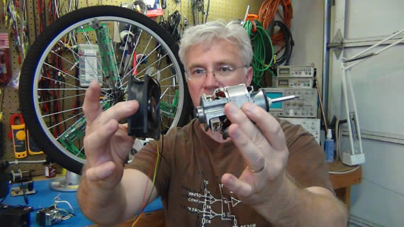
I needed to cool the below electric motor with the fan from an old computer case.
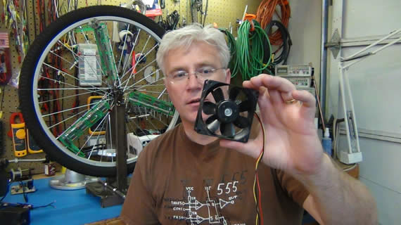
This is the 12v DC fan that needs the power supply. It has 3 wires but the yellow wire will not be used because it is just for sensing RPMs.
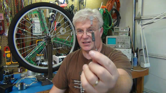
Below is the salvaged diode from a trashed microwave oven. A smaller form factor common 1N4004 would work better if you have one handy.
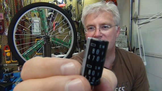
This is the 470uF 80v electrolytic capacitor I used. I salvage it from a dead power supply long ago. A rating as low as 40v would work too.
In the video I cover how the AC waveform is conditioned into DC and how to calculate true RMS when working with 1/2 rectified sin waves; which is peak voltage divided by two: (170v/2) : 85v when working with 120v AC mains.
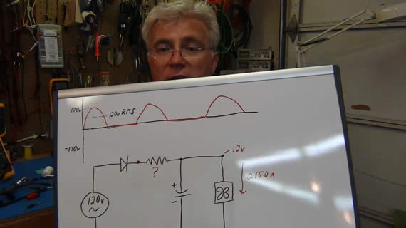
After getting the true 1/2 rectified RMS voltage after the diode I show how Ohms law is used to calculate the light bulb wattage needed to give the mystery resistance which gives us our final 12v and 150mA to the cooling fan.
V=IR
Where “V” is the voltage drop across the light bulb (85v – 12v) = 73V
“I” is the current through the circuit ~0.150A and “R” is the resistor we need to calculate.
73v = 0.15 * R
R = 73v/0.15
R = 487ohms
We can’t use any 487ohm restore because the current through it will be 0.15A and that could get real hot!
P=IV
P=0.15A * 73V
P = 11 watts
Most small resistors are only rated at 1/4 to 1/2 watts. You can buy some high wattage resistors but then you’re not using scrap.
But I happen to know that 487ohms is real close to some incandescent light bulbs when powered off 120v AC. And there will be no issue with a light bulb taking 11 watts.
To calculate the resistance of some light bulbs just run their ratings through the same equations as above.
Let’s do 100W, 60W, 40W and 25W bulbs.
100W bulb:
P=IV
100W = I * 120V
Solve for I:
I = 100W/120v
I = 0.833A
Now lets find its resistance when driven at this normal 120v AC.
V=IR
120v = 0.833A * R
Solve for R
R = 120v/0.833A
R = 120ohms
If we needed a 120ohm resistor running close to 120v AC mains power we can use a 100W light bulb
Now let’s do the 60W bulb:
P=IV
60W = I * 120v
I = 60W / 120v = 0.5A
V=IR
120v = 0.5A * R
R = 120v/0.5A = 240ohms
Now 40W bulb, which I used in my circuit:
P=IV
40W = I * 120v
I = 40W / 120v = 0.333A
V=IR
120v = 0.333A * R
R = 120v/0.333A = 360ohms
Just for completeness 25W bulb:
P=IV
25W = I * 120v
I = 25W / 120v = 0.208A
V=IR
120v = 0.208A * R
R = 120v/0.208A = 577ohms
A 25W bulb would have also worked for me but being it was getting higher than my calculated 487ohms I would rather use the lower resistance bulb. I would rather my fan turn a bit faster than too slow to cool my motor.
Another thing to consider is that I’m not going to be powering my light bulb with 120v AC. My light bulb is after my diode so it will be running on 85v DC such that it is only really on and conducting current 1/2 the time. This will change the heating and the resistance of the light bulb but not enough to cause problems with my back of the envelope style of calculations for powering a fan.
So there you have it. Three scrap components and you have yourself a hacked together 12v DC power supply.
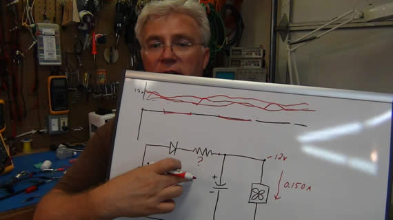
Below is an oscilloscope screen shot of my final power supply signal across the fan. Notice the 3.4v peek to peek ripple riding at the 16v DC offset. That comes out to a 1.02v RMS ripple as the capacitor charges and discharges. Not at all a good power source for some electronics, but just fine for my quick weekend hack.

This circuit could be used for any project that is not affected by the 1v RMS ripple but like I said in the video “This is just a quick weekend hack and should not be ran continues or unattended”. Things could go real bad at anytime with such a circuit and you want to be there to shut it off. This is not a safe power supply circuit and should be used with extra care. I did not use a fuse and it does expose the user to dangerously high voltage if something should go wrong. This is a hack and should only be done by somebody who knows what they are working with and can do so safely. There, you have been warned.
If you watch the full video you will see that I replaced this hacked power supply with a more stable and safe alternative in the end but the hack did get me by for the weekend and I thought it would be an interesting hack to share.
If your needs are for more or less than 150mA then you can just rework the above equations to get the light bulb size you need. Remember you can put light bulbs in series to get more ohms or parallel to get combined lower ohms just like normal resistors. Also remember to pick a diode that can handle your target current and being this is just ballpark calculations you want to take measurements at your load to validate your power conditioning is acceptable. I calculated for 12v but got 16.5v with a 3.4v p-p ripple which does work for a silly fan power supply but maybe not your project.
Thanks for following along and remember to subscribe to my YouTube Channel “toddrharrison” and my blog RSS feed.

Links for Beginners in Electronics }:-)
Archives
- April 2017 (1)
- March 2017 (3)
- December 2016 (1)
- November 2016 (3)
- October 2016 (2)
- September 2016 (2)
- August 2016 (4)
- June 2016 (1)
- May 2016 (6)
- April 2016 (1)
- March 2016 (3)
- February 2016 (4)
- January 2016 (3)
- December 2015 (1)
- November 2015 (5)
- September 2015 (1)
- July 2015 (2)
- June 2015 (6)
- March 2015 (1)
- January 2015 (2)
- December 2014 (2)
- November 2014 (4)
- October 2014 (2)
- May 2014 (1)
- March 2014 (5)
- February 2014 (3)
- January 2014 (1)
- September 2013 (2)
- August 2013 (1)
- July 2013 (4)
- June 2013 (3)
- May 2013 (2)
- April 2013 (1)
- March 2013 (3)
- February 2013 (2)
- January 2013 (2)
- December 2012 (1)
- November 2012 (8)
- October 2012 (5)
- September 2012 (1)
- August 2012 (1)
- July 2012 (2)
- May 2012 (2)
- April 2012 (1)
- March 2012 (3)
- February 2012 (2)
- December 2011 (2)
- November 2011 (4)
- October 2011 (1)
- September 2011 (1)
- August 2011 (2)
- May 2011 (2)
- April 2011 (2)
- March 2011 (2)
- February 2011 (2)
- January 2011 (1)
- December 2010 (2)
- November 2010 (2)
- July 2010 (3)
- June 2010 (2)
- April 2010 (1)
- March 2010 (1)
- February 2010 (2)
- January 2010 (1)
- December 2009 (2)
- October 2009 (4)
- March 2009 (1)
- December 2008 (1)
- November 2008 (1)
- August 2008 (1)
- April 2008 (1)
- March 2008 (1)
- February 2008 (1)
- June 2007 (1)
- November 2005 (1)
- April 2005 (1)