G35 LED Christmas Light Review and Teardown
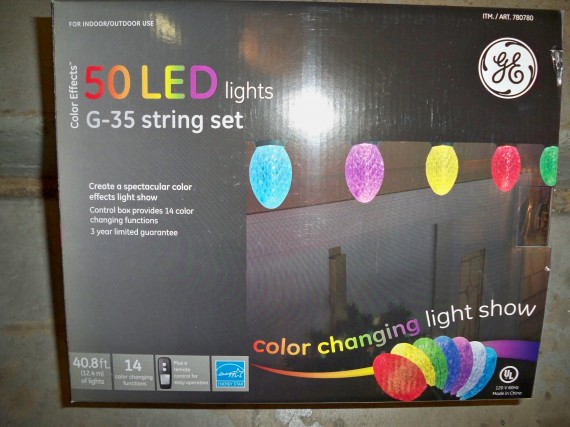
In this write up & video I review the “GE Color Effects” G35 multi colored LED Christmas lights 50 count. I will cover product details, hanging hints and show a teardown and give some links to great hacks at the end.
UPDATE 11/30/2012: My new video “G35 LED Christmas Lights – A Simple Parallel Sync Hack“
UPDATE: new links to other hackers at the end of this post!!!
You get to pick from 14 sequence patterns using a wireless controller. Hacking these lights using Arduino is already very popular so I will be linking to some good hack posts below. In a later video I will be trying some of the known hacks and some of my own.
Link to the GE product page for these lights
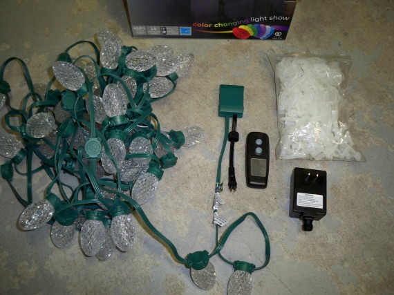
In the box you get the below:
40.8 feet of lights
50 lights spaced at 10 inches
50 rain gutter clips, 50 base clips
Radio controller with 14 light patters
CLICK TO READ ALL —>:
The light patterns are labeled on the back of the remote. Very nice touch but the 14 options are not very good. They all blink or change or race too fast. I would have much preferred a softer mood with solid color options or slower changing effects. These lights just must be hacked!

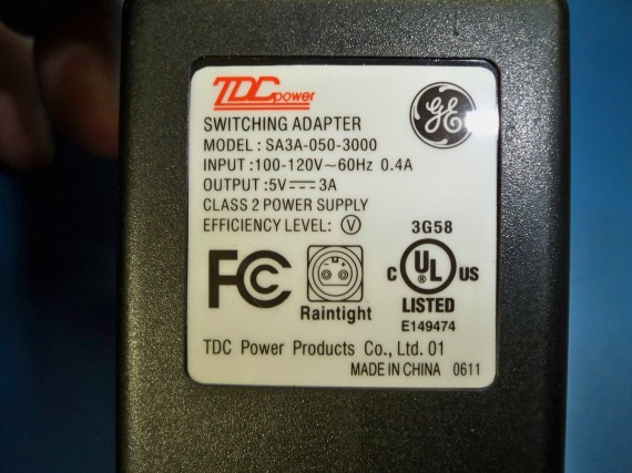
And you get a switch mode power supply 120v AC 0.4A to 5v DC 3A (later in the post I show that these rating are more than enough).
I got my lights on sale back in August at Costco for ~$60 but these 50 count lights can run from $100 to $120 on Amazon. There are other light counts and light styles in the “GE Color Effects” product line. (See above product page link for such details).
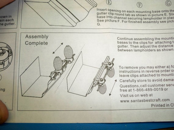
First let’s cover hanging. I was very surprised at how much care and thought was put into the hangers, which are included. You can use the hangers in several ways, either with or without the rain gutter clips.
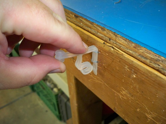
I don’t have rain cutters so I screwed these base snaps to the underside of my fascia boards.
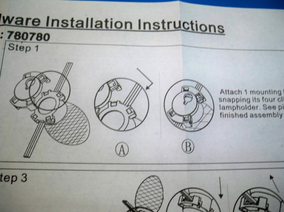
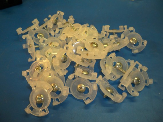
It was easier for me to sit at my bench and pre-screw the 50 clips with a short pan-head screw.
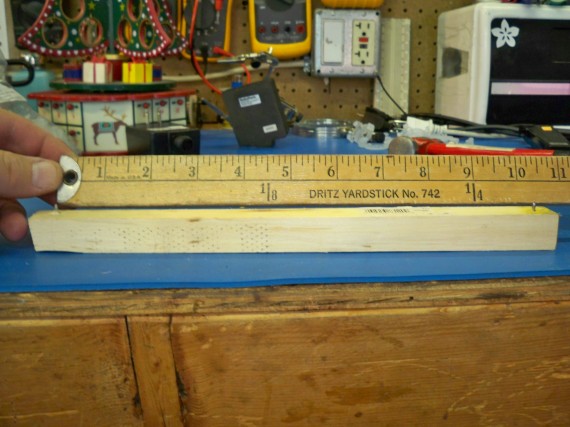
I then used an 11 inch board with a nail driven though each end spaced at exactly 10 inches. I used this jig to mark off the 10 inches between each clip. If you use bigger nails and give the jig a whack with a hammer when marking off, you will get nice pilot holes too.
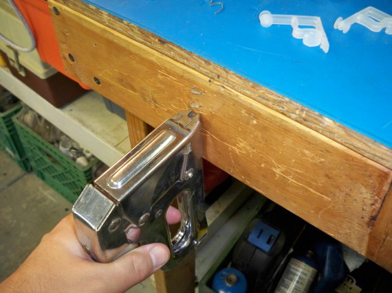
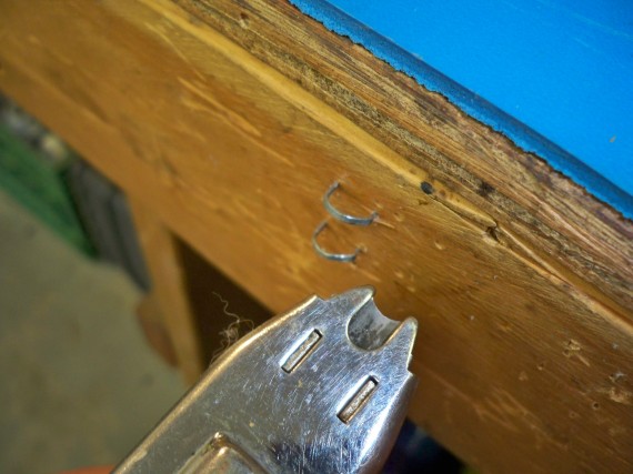
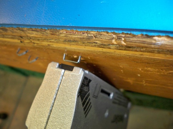
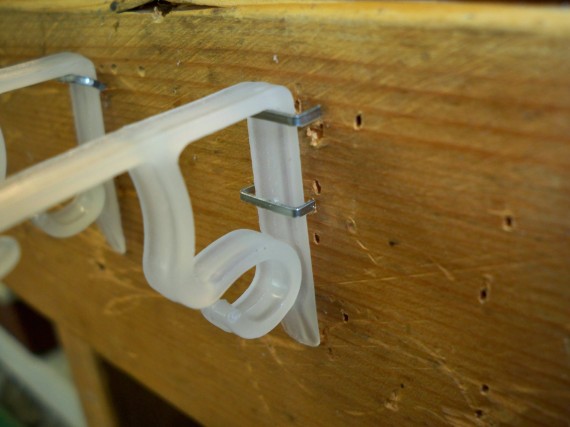
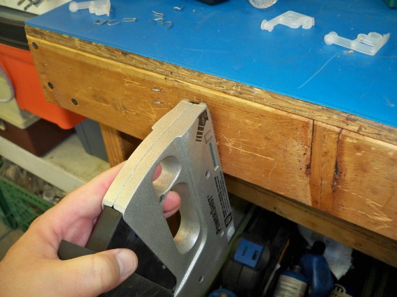
Even using this jig it was very slow going putting up 150 clips. I experimented with other ideas and the only other option for my wood fascia board would have been to use the rain gutter clips with some staples. I found that Arrows T-25 cable staples and cable stapler worked just great. These rounded staples leave just enough room to slide the clips in and out.
I also tried square staples but they didn’t work at all. They drive too deep or too shallow and there was no good way to make the square staples work.
Between the rounded cable staples and the screws I picked the screws as seen on the right side of the below photo.
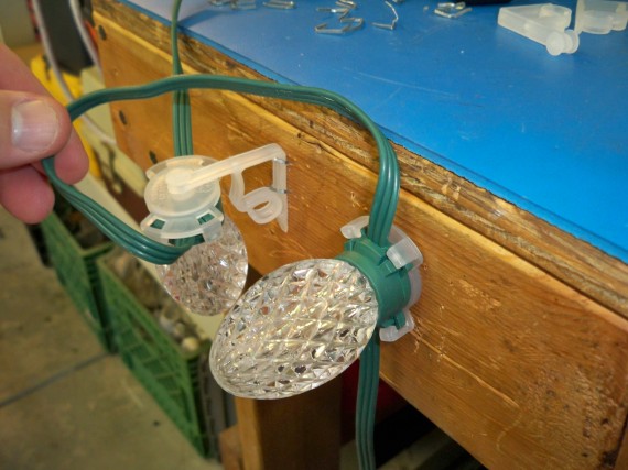
I liked the screw method because the wires are harder to see when you screw the base clips directly to the bottom of the fascia boards.
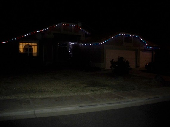
This is my house with 150 lights. Not easy taking photos in the dark. They are very bright, much brighter than you can tell in this photo. I must say I love how big and bright they are but I will have to hack these lights to get better color effects and timing.
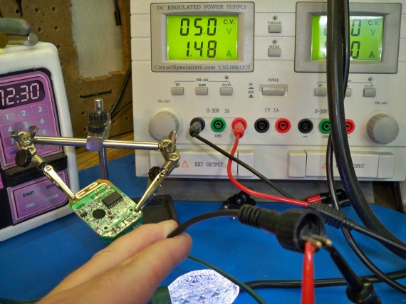
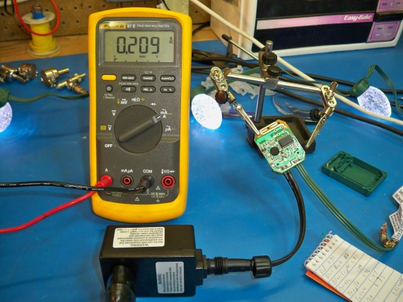
Now let’s take some measurements and take a look inside these lights. When connected to my bench supply at 5v none of the light patterns took more than 1.75A which was solid white. All the other patterns ran from 0.89A to 1.47A so this is way under the 3A switch mode power supply that comers with each light strand.
I can’t set all the lights to be solid but I was able to pick a slow enough race pattern that would race all the colors to one color before switching to the next color. Just as the 50 lights all got to a single color I would record the amps on my bench supply. Here is what I got.
Red 0.91A
Blue dark 1.2A
Blue light 1.4A
Green 0.89A
Purple 1.46A
Yellow 1.47A
White 1.75A
And the 120v AC amps when set to solid white for all 50 lights came to 0.209A, also way under the power supplies rating of 0.4 amps. So these lights come with very good rated power supplies for the loads they will be powering. This also means that running these lights is even less then I thought at 25.08 Watts. WOW that’s less power than a single old style night light for the whole strand including the controller.
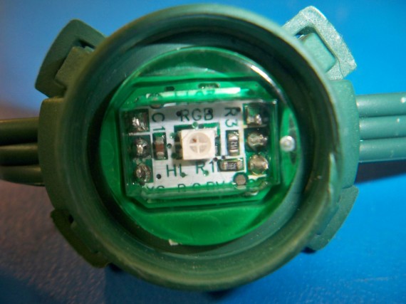
The plastic crystal defusing covers just pop right off giving you a good view of the surface mounted RGB colored LED in a sealed clear plastic case.
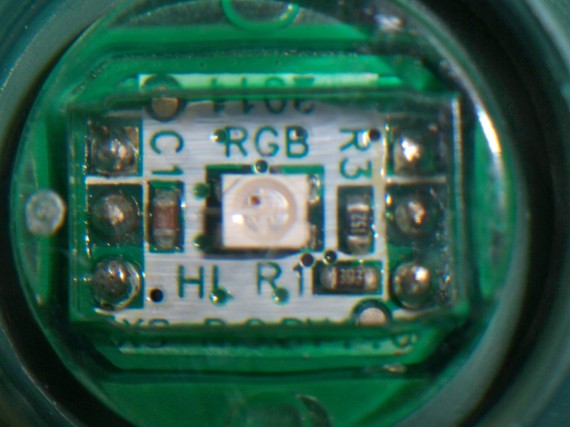
Here is a close up where you can see the PCB and the silk screen labeling. You can clearly see where the three wires come into each PCB. The two outside wires are for 5v power and ground and the middle wire is the data line that transmits the color codes to each LED.
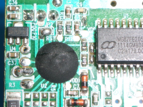
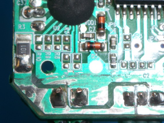
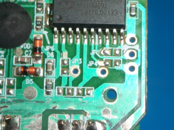
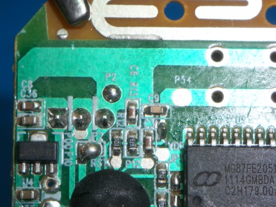
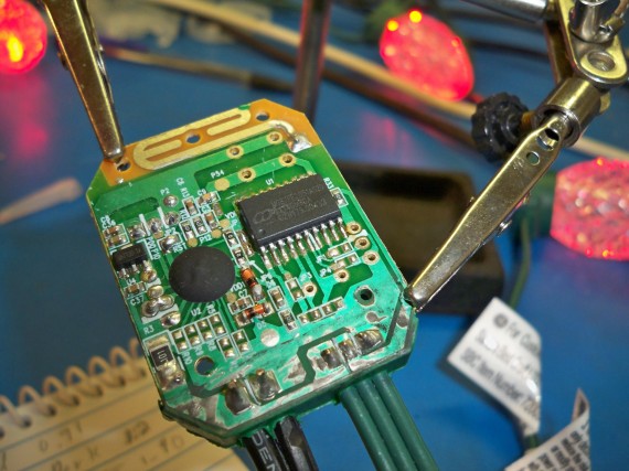
Opening up the control box reveals a single sided board with a radio control daughter board on the back side. Here are some close ups.
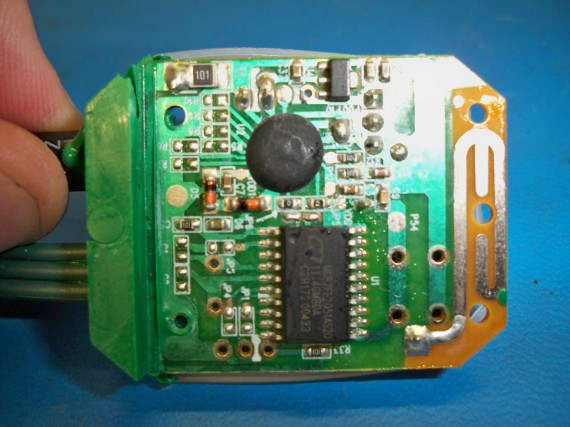
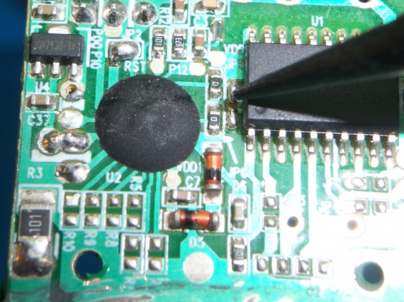
The black blob is a “Chip on board” where they glue a chip die directly to the PCB, wire bond from the die to the PCB and then seal it all up with a blob of epoxy/resin. It is a very cheap way to mass produce a product but I find it strange they also have a micro controller on the board.
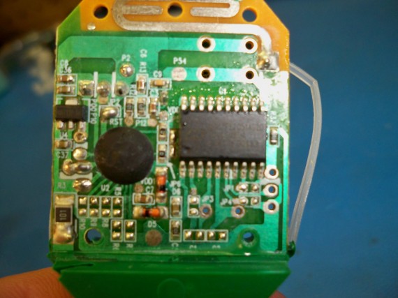
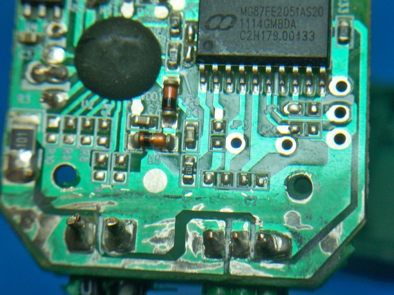
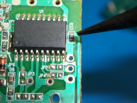
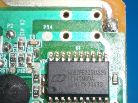
The micro controller is the surface mount SOP-20 chip (20 pins) by MEGAWIN. Here is the datasheet. http://www.megawin.com.tw/megawin_EN/UploadFiles/MG87FEL2051_4051_6051_DS_v103.pdf
MG87FE2051AS20
Here are the specs.
MG87FE/L2051/4051/6051is single-chip 8-bits microcontroller with the instruction sets fully compatible with industrial-standard 80C51 series microcontroller.2K/4K/6Kbytes flash memory and 256 bytes RAM has been embedded to provide widely field application. In-System-Programming and In-Application-Programming allows the users to download new code or data while the microcontroller sits in the application. This device executes one machine cycle in 6 clock cycles or 12 clock cycles. MG87FE/L2051/4051/6051 has one 8-bit I/O ports (P1),one 7-bit I/O port (P30~P35,P37), two 16-bit timer/counters, one PWM-timer for 8-channel PWM output, a seven-source, four-priority-level interrupt structure, an enhanced UART, a precision analog comparator, on-chip crystal oscillator (combined P42,P43) and a high-precision internal oscillator.
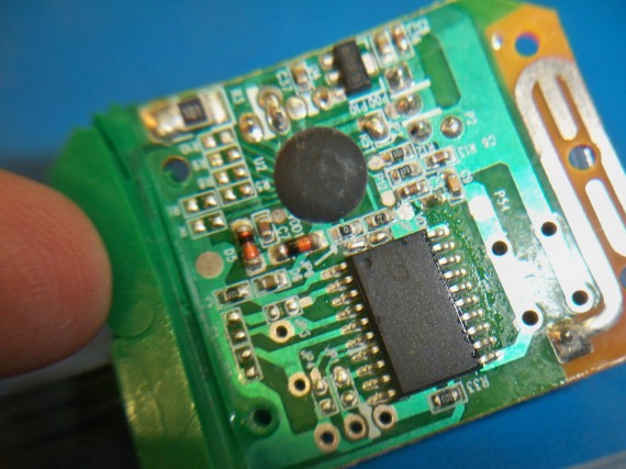
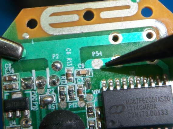
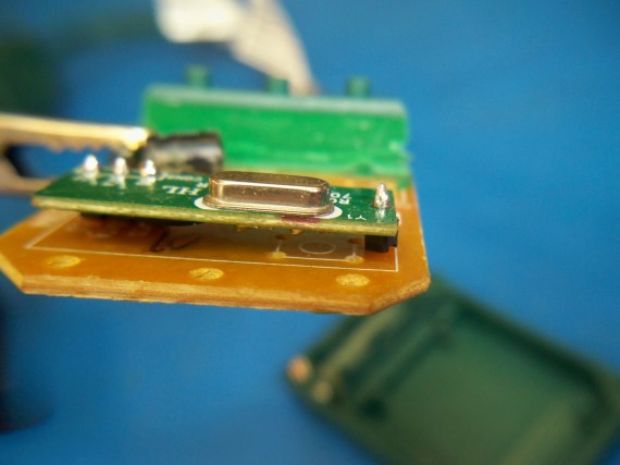
Below is the radio daughter board on the back side of the main board. The unpopulated parts you see are for a crystal for the micro controller on the other side. To save money they programmed the micro to use an internal timer instead of the quality external crystal. If they had populated the crystal and the capacitors for the crystal on the front side then I would have had no problem synchronizing two light strands and keeping them in sync. But with the low grade internal timer, each chip will have a different idea of time and even when you do get two strands in sync the poor internal timers will just drift and the light strands will be all out of whack with each other in under an hour. Unfortunately you can’t just populate the crystal yourself because the micro is internally set to look at the internal timing not an external crystal, oscillator or resonator.
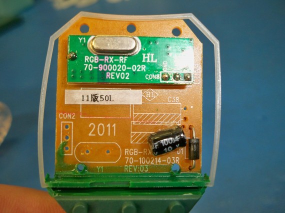
Under this daughter board I could see another “chip on board” so this radio board was setup for some major mass production. Under this board I can see the silk screening for a button (SW1) so this board can be used with our without the radio option.
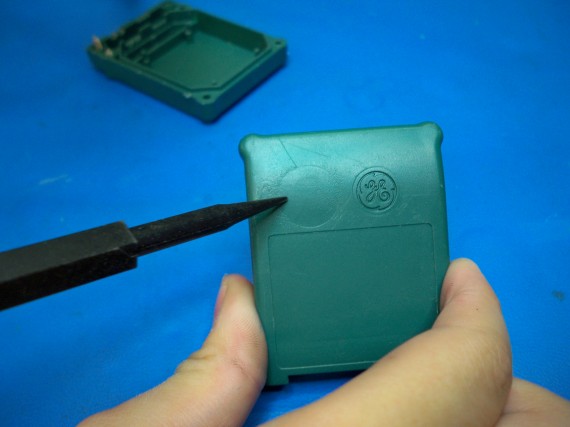
And you can see the in the plastic over it is setup for a hole to be punched for a button. I would guess this is for other products GE sales that don’t have radio control and you just push a button to switch patterns or hold the button for a count of “?” to turn on and off.
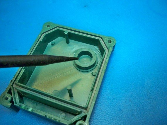
Button hole on front cover if punched.
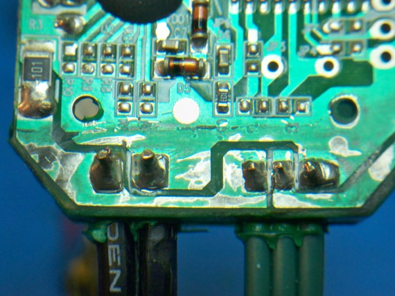
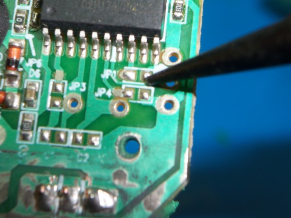
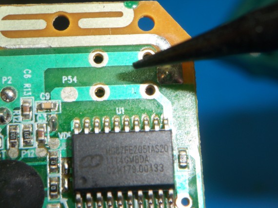
This would be where the button would be mounted on the PCB board if this was not a wireless model. I was able to short these two traces with a quick flick to change patterns and a longer short did turn off the unit as I suspected.
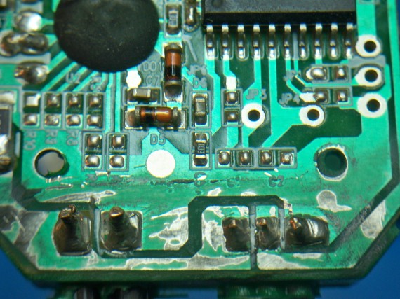
Now for the deep hacking folks. I wanted to take close up photos of the traces in the hope that maybe a more easily programmed SOP-20 micro could be implemented. Maybe some ATmega or PIC would be dropped on board and programmed in place keeping the board and its radio control. The crystal and capacitors could also be populated for better timing. Then these strands can be synchronized as well as programmed with better patterns. (Click for larger photos)
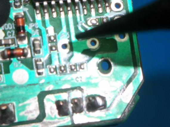
If the crystal is populated on the back side here is where the legs come up. And just below you can see C1 and C2 which would be the capacitors home needed for the crystal.
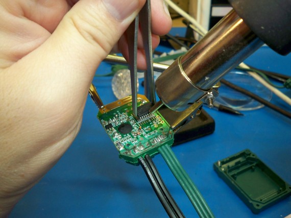
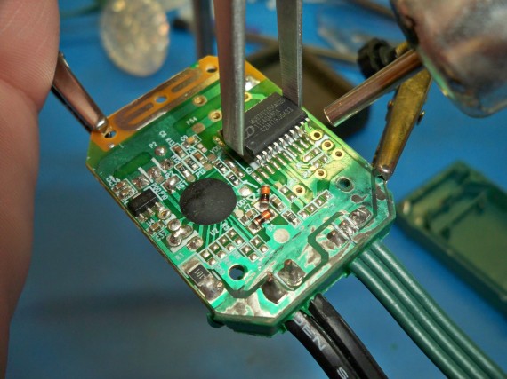
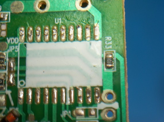
I know we need to see the traces under the IC so I used my hot air wand to remove it and take photos.
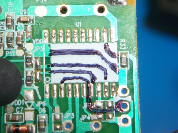
Below I tracked the copper just incase it was not clear where the traces ran in the above photos. This helps a ton being we know what connects to each and every pin of the micro controller. This is a single sided single layer board so nothing hard really.
Now the IC is back on and as you can see the lights are running fine.
That is it for my review and teardown. Now for some links to others that are doing some hacks for these lights.
DigitalMisery.com has an open source drop in wireless replace board for these lights. WOW, you can’t ask for more than that. He does not sell the boards yet but keep checking his site to see if he gets a Kick starter going or just follow his open source documents and spin your own board. He links to his code and the Arduino library’s “G35Arduino”
DeepDarc.com put up some amazing engineering details on these lights and reverse engineered both the radio protocol and the protocol used on the LED data bus. You must read his post if you’re going to be hacking these lights. He also shares his code and other very useful tips.
Keithsw has some great stuff synchronizing 6 strands and shares his control code, Arduino circuit and a PC software simulator program to help design the layout and patterns. Here is his short (video).
CheerLights is an ioBridge Labs project that allows people all across the world to synchronize their lights. This sit gives all the hacking details and you can play along even it you don’t have lights by tweeting a color to @cheerlights and watching on ustream.
Jim at Jim’s G-35 Project Page makes his own control board using a PIC18F2620 micro controler.
If I have any of my own hack updates I will link to them from here and under “All Postings” with the title “G35 LED Christmas Light…”
UPDATE 11/11/2012 for EXTRA LINKS:
Good arduino example with new library – (digitalmisery.com)
11/21/2011: Added new Arduino IDE 1.0.1 supported code – (digitalmisery.com)
(github.com/MarkEMarkEMark/G35-MEO-Programs)
UPDATE 12/18/2012 for EXTRA LINKS:

