
Today I’m going to show a video on how to troubleshoot and repair a timer control. I will be sharing my evaluation of the problem and my final solution. Along the way I demonstrate three different methods on how to remove electronic components and I give some hints to make it easier. I show how to fix a fused relay and in just this blog posting, not the video, I also document how to test a bipolar junction transistor (BJT).
The three methods I cover are:
1) Manual desoldering pump at (adafruit.com)
2) 30 Watt Electric desoldering Tool at (amazon.com) or (elexp.com)
3) Solder wick at (adafruit.com)
If you don’t care to watch the video I will summarize below.
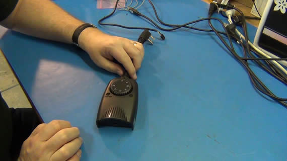
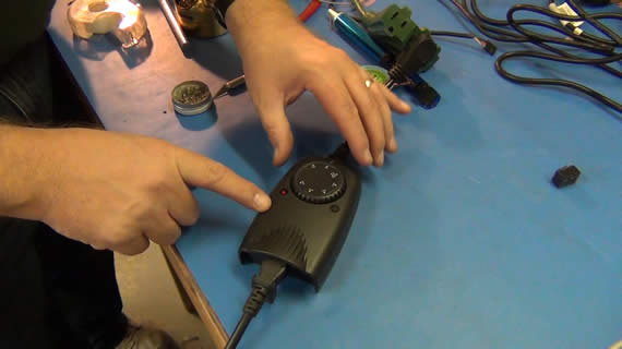
I have an exterior timer control that turns my Christmas lights on at dusk and off after 6 hours. I noticed they never turned off one day and thought I had left the timer control set to the ON position. But no, it was set to off 6 hours after dusk. I then set the selection switch to OFF but still it was on. I unplugged and plugged it back in but got the same problem. It was time to go to the electronics bench.
CLICK TO READ ALL —>:
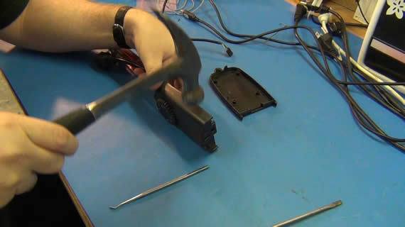
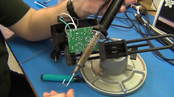
NO SCREWS!! Damn now I have to bust this open. That alone might mean this is not going to be fixable. A few swift whacks with a hammer along the glued seams and it popped open. NICE! If I can fix it I can glue it up and be back to its water tight condition.
![]()
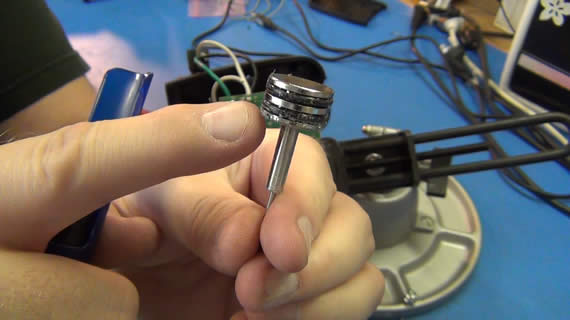
The board was single sided and all through hole construction. A quick glance around the board and I spied what looked like a fried transistor wired up to turn a 15A 125VAC relay on and off. The bottom of the transistor was all bubbled and I was sure it was a dead short causing the relay to be on all the time.
![]()
Above is a close up of transistor.
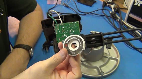
I removed the bad transistor using solder wick for one leg,
desolder pump for another leg
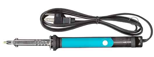
and for the last leg I used a 30 watt electric desoldering wand. This electric desolder wand is under $30 at most places and is a super greate tool IF YOU KEEP IT CLEAN! I used these three methods just to show the video viewers how each method works. The hints I give along the way are to set your solder iron to max when using solder wick and preheat the solder before applying the wick. I have also read that adding lead based solder to the joint in advance also helps the lead free solder wick up into the braid better.
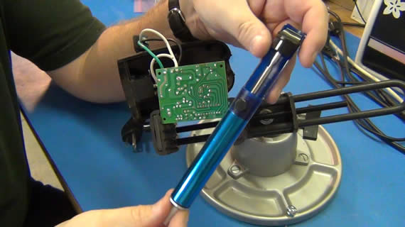
This is the plunger in the desolder wand and it needs to be cleaned often!
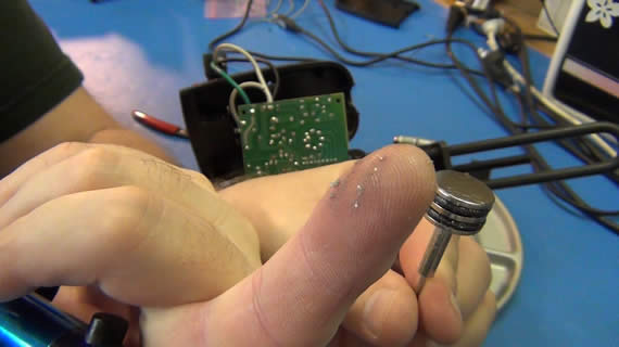
This stuff will get on the o-rings and keep you from having a strong solder sucking vacuum.
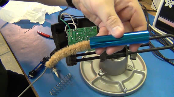
I demonstrate how important it is to clean desolder pumps by taking one apart and using a bottle brush to get all the old solder scrap out. Then add a little Vaseline to the o-rings before reassembling.
Finally for the electric desolder pump/wand combo you must clean the hole in the tip with a wire that comes with the tool. If you follow these tips your component removal will be easy.
After getting the transistor out I take down the component number so I could lookup if it was a PNP or NPN and what leads were emitter, collector and base in the package. With this information I use the below transistor testing image to test if the transistor is good.
Photo from: “Using Your Meter” by Alvis J. Evans at (amazon.com) I did alter this image to be easier to read and use for DMM diode mode testing.

These images are really for using an ohm meter but if you put your DMM in diode test mode you get the same test except you’re testing the PN junction between the positive and negative DDM test leads instead of a straight up resistance. Where you see “LOW” you should get a forward bias diode junction pass on your DMM indicating a very low electrical resistance and where you see “HIGH” you should get OL on your DMM meaning “open loop” junction or very high electrical resistance.
If your type of transistor, NPN or PNP, fails one of the tests in any direction then it is bad and needs to be replaced. Please note that this is not a complete electrical test of a BJT transistor. A transistor can have other issues like high leakage and in circuit modes of failure that are beyond the scope of what I want to cover here. But if it fails this simple test it is bad and you can confidently know you have to replace the transistor.
![]()
My transistor passed with flying colors! So my problem was not this transistor and closer inspection revealed the melted plastic by the component’s legs was just some glue used to seal the case.
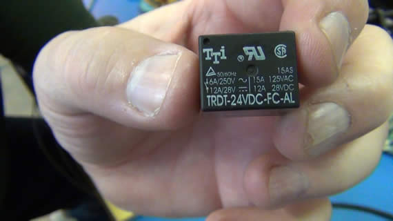
Nothing else controls the relay on my board so it must be the relay itself. I looked up the relays datasheet on the internet and found its pin out configuration then tested between the in and out of the normally open (NO) pins.
Sure enough it was a dead short so the relay’s contact points must be fused together.

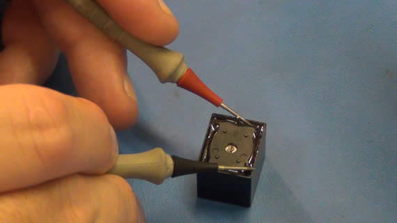
Just for a bit of fun I used my Dremel tool and cut off the plastic top of the relay to see the failure. Sure enough the points were fused.
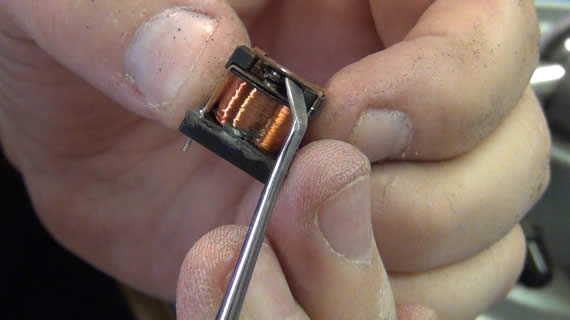

I popped the relay’s contact points apart and cleaned them up with some metal grade sandpaper. After tested the coils I soldered it back into the circuit along with the transistor I removed.
A quick test with my radio as the load showed the timer control was now working great!
I don’t want to put the repaired controller back in service knowing the relay has already had such damage so I will order a suitable replacement the next time I make a bulk parts order. For a couple of bucks I will have my Christmas light timer control back in service and not in a landfill.
UPDATE Dec 24th 2011:

My replacement relay has arrived. I dropped it in, sealed the box with hot glue and put it back in service. It is working perfectly. I replaced the relay with a 10Amp instead of the original 15Amp but that is just fine for my Christmas lighting plus it was cheaper at just $1.75 USA. The new relay was SPDT (single pole double throw) so I had to snip off the NC (normally closed) pin.
Thanks for visiting and don’t forget to subscribe to my YouTube channel if you like my videos.

Links for Beginners in Electronics }:-)
Archives
- April 2017 (1)
- March 2017 (3)
- December 2016 (1)
- November 2016 (3)
- October 2016 (2)
- September 2016 (2)
- August 2016 (4)
- June 2016 (1)
- May 2016 (6)
- April 2016 (1)
- March 2016 (3)
- February 2016 (4)
- January 2016 (3)
- December 2015 (1)
- November 2015 (5)
- September 2015 (1)
- July 2015 (2)
- June 2015 (6)
- March 2015 (1)
- January 2015 (2)
- December 2014 (2)
- November 2014 (4)
- October 2014 (2)
- May 2014 (1)
- March 2014 (5)
- February 2014 (3)
- January 2014 (1)
- September 2013 (2)
- August 2013 (1)
- July 2013 (4)
- June 2013 (3)
- May 2013 (2)
- April 2013 (1)
- March 2013 (3)
- February 2013 (2)
- January 2013 (2)
- December 2012 (1)
- November 2012 (8)
- October 2012 (5)
- September 2012 (1)
- August 2012 (1)
- July 2012 (2)
- May 2012 (2)
- April 2012 (1)
- March 2012 (3)
- February 2012 (2)
- December 2011 (2)
- November 2011 (4)
- October 2011 (1)
- September 2011 (1)
- August 2011 (2)
- May 2011 (2)
- April 2011 (2)
- March 2011 (2)
- February 2011 (2)
- January 2011 (1)
- December 2010 (2)
- November 2010 (2)
- July 2010 (3)
- June 2010 (2)
- April 2010 (1)
- March 2010 (1)
- February 2010 (2)
- January 2010 (1)
- December 2009 (2)
- October 2009 (4)
- March 2009 (1)
- December 2008 (1)
- November 2008 (1)
- August 2008 (1)
- April 2008 (1)
- March 2008 (1)
- February 2008 (1)
- June 2007 (1)
- November 2005 (1)
- April 2005 (1)