The (SARC) Superstition Amateur Radio Club of Mesa, AZ needed to replace their UHF/VHF repeater antenna and repair the hard feed line which had a large dent in it from years back. This video shows the club taking down the tower, replacing the antenna and fixing the hard line.
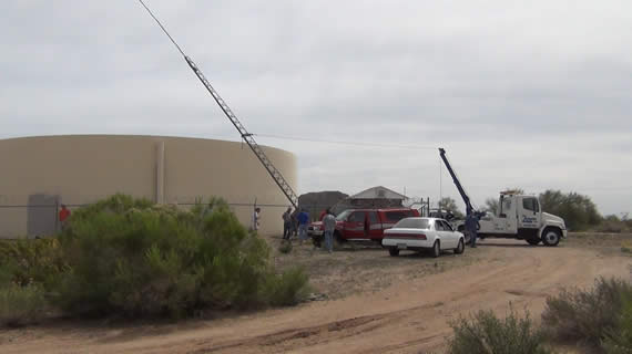
One member volunteered to climb the tower to connect the strap and tow cable. This tower’s base is on a hinge so to bring it down you only need to remove some large bolts.
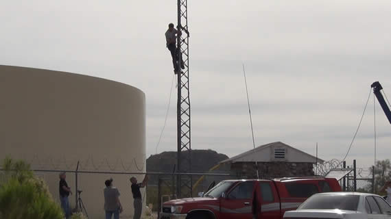
A local towing company volunteered their crane truck and a driver for a couple of hours. Thanks Apache Sands towing it was greatly appreciated. Some more volunteer members pulled on a counter rope and the tower is on its way down at the command of the tow truck operator.
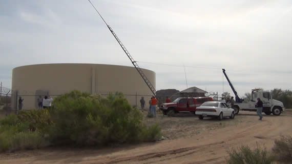
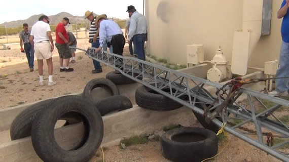
The tower is lying down nicely on some old tires.
…
CLICK TO READ ALL —>:
…
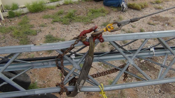
This is a close up of the connection made to the tower for the tow cable.
Members go to work removing the old antenna and fixing the hard line that feeds the UHF/VHF signals to the antenna. In the below photo a member is bringing the new antenna.
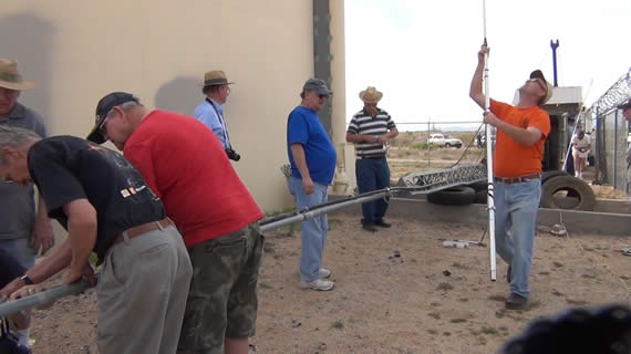
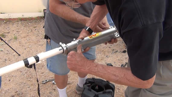
The new antenna is now being mounted to the mast. The new antenna is ~18 feet, the mast is ~19 feet and the tower stands ~38 feet so the overall structure tops out at about 75 feet.
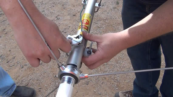
Below is the large copper grounding wire being connected to the antenna. This ground runs all the way to the base of the tower where it is then connected to ground rods.
We removed the last 18 feet of hard line from where the damaged point was to the top and replaced it with coax. There will be some signal lost but not enough to make any noticeable difference. Terry details how to attach the hard line connector which adapts the large hard line to a normal “N” style connector.

Install O-ring and some grease.
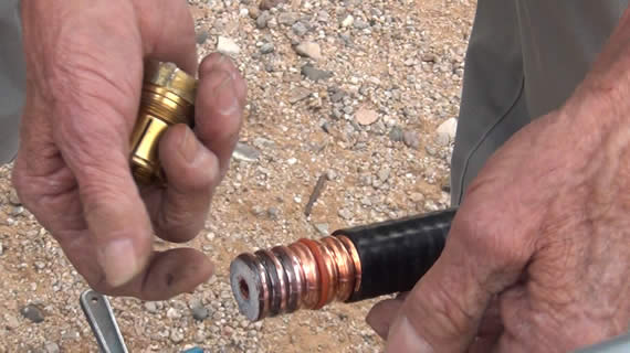
The first part of the connecter is now on and the outer copper has been flared by hand using a needle noise pliers.
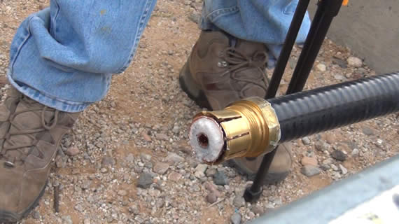
The center conductor pin was screwed into the center of the hard line copper core. Some more grease was applied to the threads and flare point.
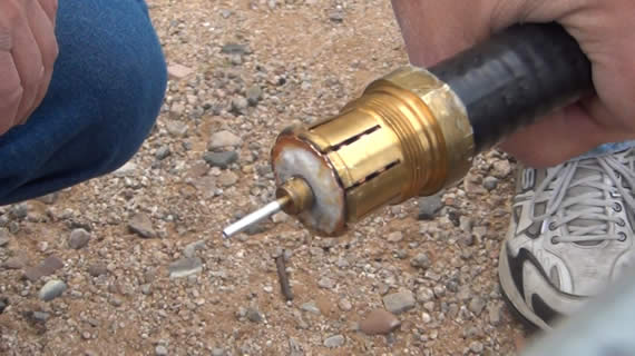
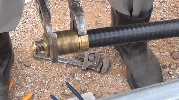
Terry then put the cap on and tightened up the connector.
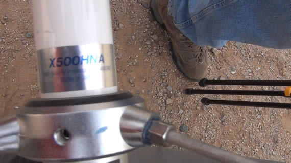
The antenna we installed was a X500HNA made by Diamond and made in Japan.
The “N” connector and coax got some grease and protective rubber tape.
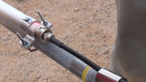
This is just a stainless steel sleeve that covers the connector at the base of the antenna.

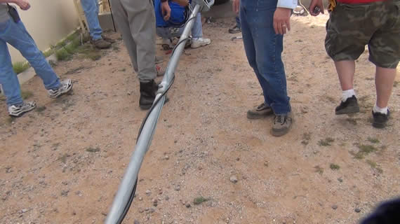
The coax was lazy wrapped around the mast instead of clamped.
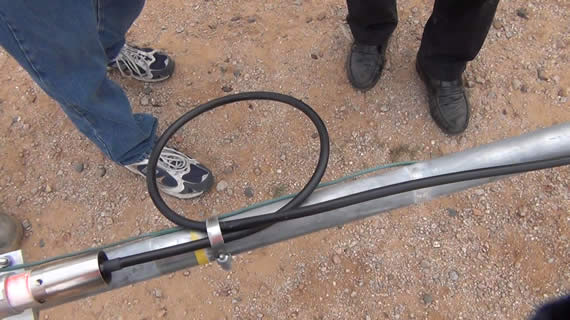
A loop of about 6 to 7 inches needs to be put in the coax just before going into the antenna to help reduce unwanted shielding currents that can exist at UHF/VHF and most likely for other reasons not explained.
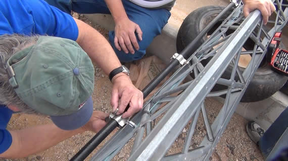
The hard line that remained got nicely clamped to the tower.
Terry now details how to attached a new “N” connector to the new coax cable. He firsts preps the wire and slides on the crimp sleeve.
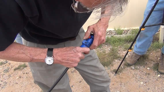
He sizes up the cut back on the shielding and exposure of the center conductor for the center pin.
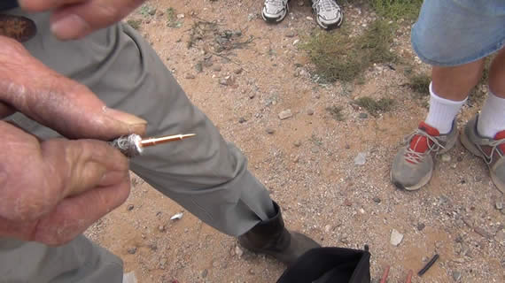
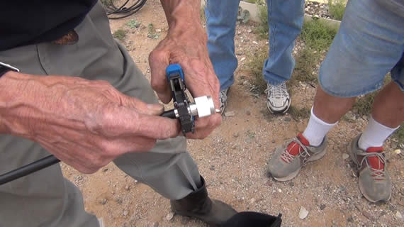
Then Terry crimps on the new center conductor.
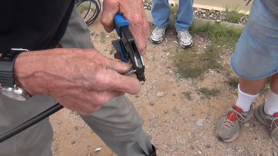
Then he puts on the outer part of the “N” connector over the shielding foil but under the braided grounding wire.
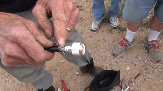
A simple plier is used to slide the crimp collar up and over the braided grounding wire.
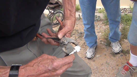
Terry makes one more crimp to secure the collar of the “N” connector to the coax.
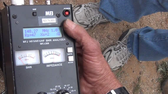
A quick check with an antenna analyzer confirms that both UHF and VHF are looking good even in this horizontal position.
The “N” connecter can now be attached to the hard line
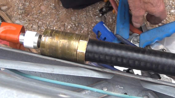
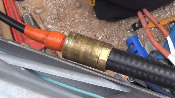
Terry applies orange rubber tape around the “N” connector.
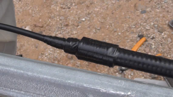
Then he applies generous amounts of black rubber tape to make sure no moisture ever gets into the connector.
The crane truck makes short work of brining the tower back up into position.
And we are done as soon as the bolts are installed at the base and the climber removes the cable.
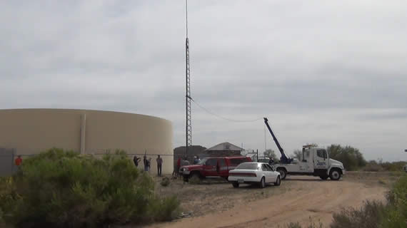
Everything worked great with the repairs and antenna install. Thanks to everyone’s help the job was done in just about 2 hours.
If you are in the Mesa, AZ area you can listen in to this repeater and if you’re a ham you are welcome to use the SARC repeater even if you’re not a member:
VHF on 147.12MHz (+) PL 162.2Hz
<or>
UHF on 449.60MHz (-) PL 100.0Hz
Thanks for joining.
Todd

