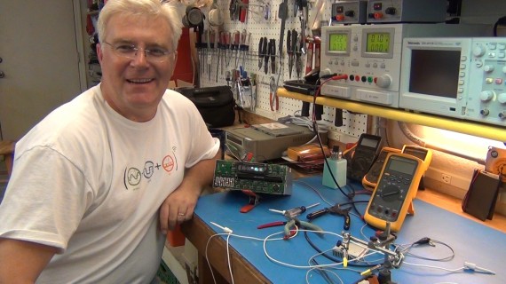
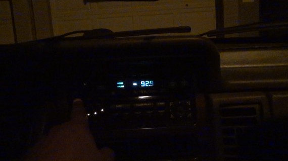
This is an epic video on all my efforts to fix my radio out of my 1994 Jeep Grand Cherokee. It is a limited edition Jeep with a very nice CD/Radio sound system but for about 10 years now the vacuum fluorescent display (VFD) has been dead although the radio and CD work fine. This meant my only headache was I never knew what station I was on. But after setting the stations who cares, right? Well it drove my daughter nuts because she likes to channel surf and after having the battery disconnected it was a challenge to find and set the stations again.
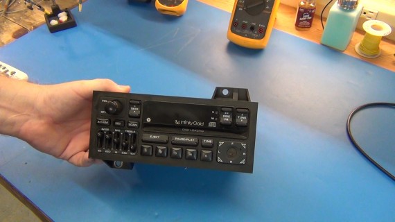
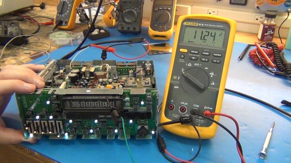
This is the radio/CD player that I need to fix. Only the display is broke so how challenging could that be? VERY! I guess I’m not too good at fixing VFDs.
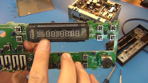
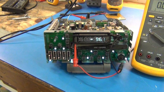
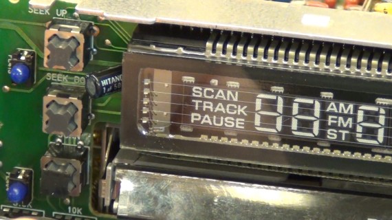
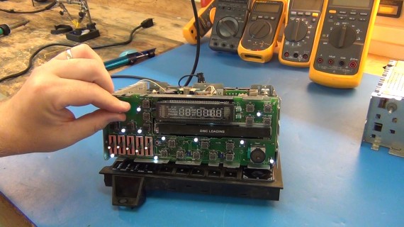
This is the display that does not seem to be getting power or functioning.
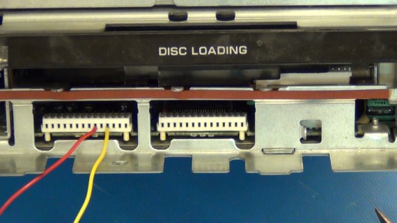
After unplugging the display panel PCB I had access to the board headers off the main radio. The silk screening on the display panel PCB had labels that told me the pins that were for 5v and 12v. I powered up the radio using my 12v supply to simulate the car battery being connected then used some jumper wires to probe 5v and 12v pins going to the display panel PCB. All checked just fine.
CLICK TO READ ALL —>:
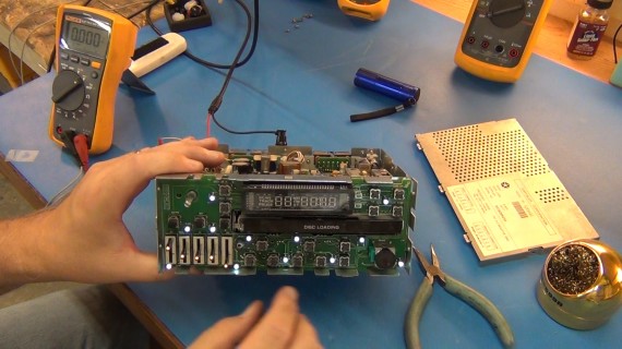
With the display board plugged back in and the radio powered all the lights work and the radio still works the same. I probed some other voltages on the display panel board and everything checked except I didn’t find any voltage across the VFD cathode filament pins. It seems the radio has a dead heater driver for the cathode filament which should be producing the thermionic emission of electrons needed to cause the fluorescent tracks to fluoresce.
I wanted to know if the data pins to the display were being driven by the control chips correctly so I put the radio in scan mode and probed one of the lower display data pins and sure enough the voltage was changing form 12v to 0v as the radio was scanning through the frequencies. I could have used my scope here but really a DMM is all you need for this test.
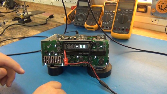
Time to do something crazy! I figured I would just connect my 2nd DC power supply to the VFD cathode filament pins and slowly turn up the power. This would put 100mA through the filament and should cause the thermionic emissions we need. Yes, I know these filaments are normally driven by a variable duty cycle pulse. My frequency generator could easily create this signal and it can source 100mA but DC will work to at a low voltage. We just need to test if the only thing missing here is the thermionic emission to make the display work so the DC test is fine. My biggest concern is adding this power and there being some kind of short to ground in the circuits going to the filament pins which will POOF when I add an external source. If no such short exists then the low ohm filament should be the only thing that draws power. I turned up the voltage real slow on the 2nd power supply and watched thes current readout to be safe. I could have taken the board off and cut the traces powering the filament to make this a safer test. Well, IT WORKED! I only had to add ~1v at ~0.1A so the filament is about 10 ohms when up to temp. Before it’s up to temp its resistance is ~3 ohms.
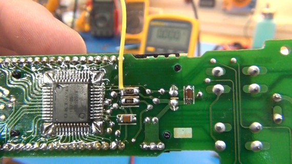
Below I have soldered a jumper wire to what I think is the VFD cathode filament driver pin. I most likely have this wrong as you will see in the video but this is where I was here. I wanted to test the driver voltages at different points but to probe it live I had to use this soldered jumper wire trick on the back side of the display board before plugging it into the radio.
I did find some voltage but after some passives closer to the VFD cathode filament pin the voltage dropped to zero. Later I found I was tracing wrong and had been testing the ground side of the VFD cathode filament (my bad). There was some vias I missed and it was very hard to trace with the display covering ~50% of the tracks.
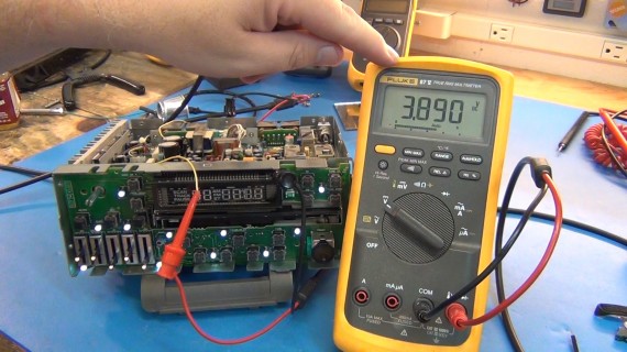
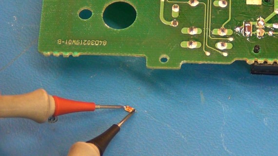
I took off every passive involved with powering the cathode filament and they tested fine. They tested fine in circuit too but I wanted to make sure I didn’t miss a simple fix. Below I’m testing a SMD 6k resistor.
In this photo you can see the 5 parallel cathode filament wires hovering over phosphors tracks in the display. This is what is not getting proper power by one of those two control chips on the back side of the board.
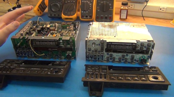
I went to the wrecking yard and got a smashed up radio from a 1993 Jeep that seemed to match my sound system exactly. I paid $17 and was happy because I only wanted the display board. Unfortunately the next year, 1994, they had a full re-spin of this display board and it can’t plug into my working radio and the wrecking yard one was too smashed up to be fixable.
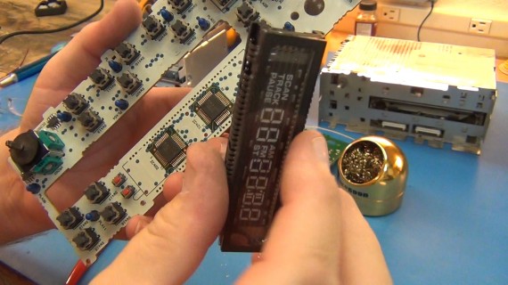
But maybe I could go down the rabbit hole a bit farther and salvage the chips off the wrecked unit’s display board. I had to unsolder the display on the wrecked unit because the control chips were under the display in the 1993 spin. Could this get any more difficult?
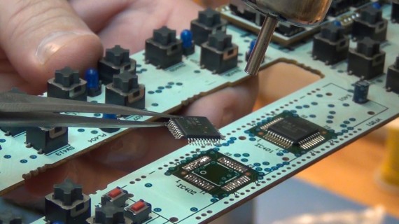
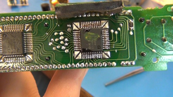
YES! Sadly only one of the chips was the same part number as on my display board and it was the one I didn’t think was bad anyway. But I had to try so here I’m using my hot air rework station to remove the usable TQFP chip.
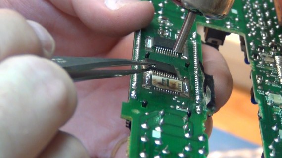
Then I removed the matching chip from my display board.
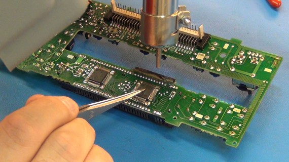
Finally some hot air and flux to mount the replacement chip.
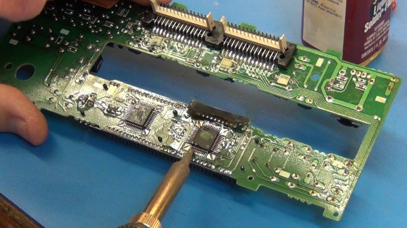
I got a bit happy with the hot air pressure and caused a few solder bridges so here I’m reflowing the pins to remove the solder bridges.
Close-up with a magnifier and all looks good.
The display board is back in my radio but no luck, same problem. Must be the other chip and I don’t have a replacement.
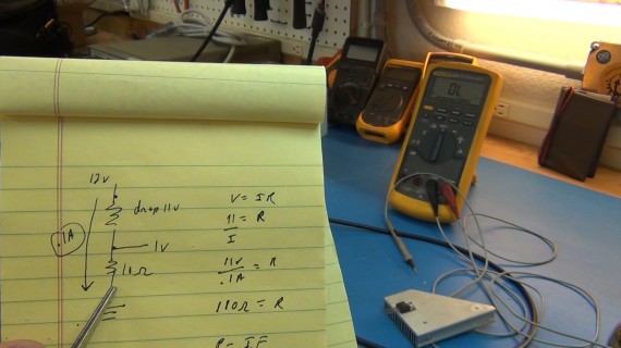
We can still power the faulty part of the circuit with 1V and 0.1A to get it working. The dumbest, emphases on dumbest, way to get power to this part of the circuit and get this working is to use the radio’s 12V supply and a dropper resistor.
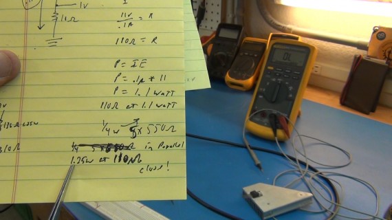
Some simple circuit math shows us what we need. From my tests I know I need 1V DC across the cathode filament and 0.1A of current. Current in a loop is always the same so both my filament and my dropper resistor will have 0.1A running through them. I have 12V supply and need to drop the 12V by 11V to get the 1V at the input of the filament. V=IR gives me my dropper resistor value (R = 11V/0.1A) => 110 ohms.
Easy enough but what about power, will a ¼ watt resistor work? No. For power dissipation in the dropper resistor we use P=IE (easy as pie), but in today’s circuit math they changed the E from Electromotive Force to V for volts. Ok, so the equation changes to P=IV but I always find it easy to remember the older mnemonics. This shows us that (P=0.1A x 11V) => 1.1 watts. So my 110 ohm resistor has to be rated for at least 1.1 watts. I could use five 550 ohm ¼ watt resistors in parallel which will give me a 1.25 watt rated cluster at 110 ohms but that is pushing the wattage rating.
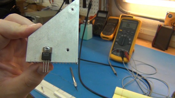
I played with a circuit using a LM317 variable voltage regulator but the questions and my tests showed me the low limit was going down to 1.25V because of the internal 1.25 volt reference in the LM317. No luck there because that would have produced a lot of heat at 1.25V not to mention the display would be way to bright at that voltage.
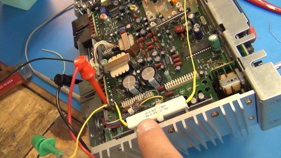
I did think about hacking together one of my micro controller chips with a proper filament drive signal circuit but I have spent too much time on this project already and a dumb ass dropper resistor rated at 10 watts will do the job. I found a 100 ohm 10 watt ceramic resistor in my parts bin. I had 5 or more of these resistors, some new some salvaged, all rated at 10% so I just measured each and picked the one closest to 110 ohms. I believe the one I picked tested at 109 ohms and was therefore the best fit. I zip tied it to the left/right channel amplifiers because they were clipped to a large heat sink on the side of the radio and won’t mind the extra 1.1 watts of heat.
There we go, I’m not happy with my dumb ass voltage divider power supply solution but I’m smiling because it is working and will most likely work for years like this. I ran it on the bench like this for a few hours with no problems.
Then I put it back in my Jeep. It sure was nice to see that old radio display working again after so many years. I will report back if it dies of over heating or fails in any other way.
There are so many ways these devices can be instantiated. Some use a hot cathode filament voltage of 1.5 to 3 volts but that may or may not be an AC signals for larger displays. You will need a grid voltage from teens to tens of volts depending on model. And of course a driver signal that puts data to the other pins to activate the digital values to display. Here are some research sources:
http://en.wikipedia.org/wiki/Vacuum_fluorescent_display
http://www.tubeclockdb.com/vfd-tubes/100-simple-vfd-tester.html
http://www.kerrywong.com/2013/06/13/a-diy-vacuum-fluorescent-display-driver/
http://hackaday.com/2008/12/25/working-with-vfds/
Thanks for visiting and remember to subscribe to my RSS feed above, if you use a reader, and subscribe to my YouTube channel (toddrharrison).

