
This will be a 7 part blog posting on one project at varying stags of completion that my daughter and I worked on over our fall vacation.
This is part 1 but you can (see parts 2 -6 here)
My daughter wanted to install a POV (persistence of view) device on her bicycle spokes which would allowed her to draw images on her laptop and upload the drawings to be displayed in her spokes as she rode around at night. I found the best kit for this at Adafruit.com called SpokePOV.
Below is a short video of the final assembled and functioning kit with a manga type winking happy face animation my daughter created in Photoshop.
My digital camera set to video record makes the image appear shaky and flashy but this looks a ton better to the human eye. I guess you will just have to take me at my word for now, but later I will try to get better video using a real camcorder.
The seven blog posts I’m planning, starting with this one, will be:
1) Assembling the 3 SpokePOV boards & setup for single sensor triggering
2) Mounting an adjustable magnet on the bike frame for SpokePOV trigger
3) Building bench testing rig for SpokePOV
4) Programming images and setting the SpokePOV board offsets
5) Halloween image uploads with video of SpokePOV in action
6) Troubleshooting and resolving SpokePOV image skew issue
7) Fixing image skew issue using my own creation called “Corrective Raiser image Board” (CRiB)
PART 1) Assembling the 3 SpokePOV boards & setup for single sensor triggering
My 17yr old daughter did all the assembly and photographing. She has been doing PCB board assembling since she was six years old and is one of the best at using a solder iron I have seen, including myself. She only burnt herself once but that was actually my fault because I was holding the iron and pointing at something. So truthfully I burnt her, she didn’t burn herself.
CLICK TO READ ALL —>:
If you order this kit you can pick your color LEDs (Red, Yellow or Blue). We picked red. The blue kit costs more and you will need to run it with 3 AA instead of two. You can get just one SpokePOV board but you have to peddle like a mad man to get a good image or animation so you will want to buy the 3 board kit for $99 and while your at it select the upgrade to a USB programmer for $14 because it is really a lot faster programmer and much easier to use when uploading your images.
Once you get your kit you will want to read and follow all the instructions on Ladyada’s SpokePOV project build and user manual site. This site has excellent assembly instructions and photos for this kit as well as all of her other kits. When following the website’s instruction remember to use the navigation menus and submenus on the left for the given project, but you can use the navigation menus at the top for moving around to other projects. If you get in a jam you will also have the privilege of excellent community support and company support at Adafruit’s Forum. Here is a direct link to the SpokePOV Forum.
From here on I will just pop in each photo from the assembly stages with a blurb on what was added to the PCB and sometimes very general functionality.
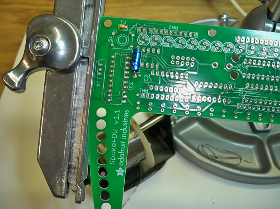
She is off an going with a couple of capacitors installed.
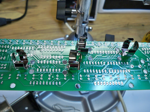
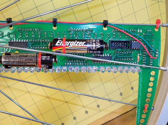
The battery clips are now installed. If we had blue LEDs we would have needed a third set of AA battery clips but we have the red LEDs which only need 3v for the whole circuit.
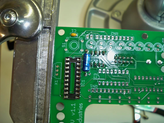
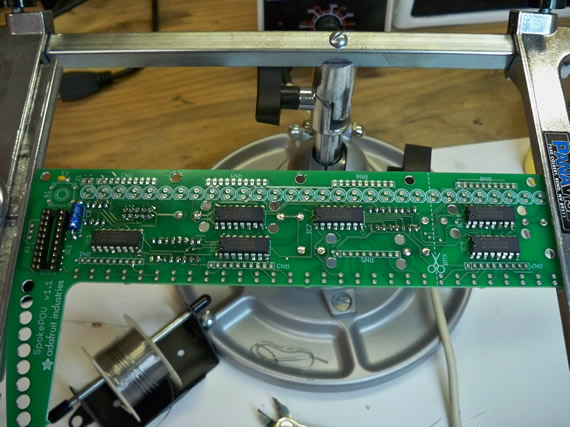
The micro-controller (MC) chip socket is now on. This socket makes it amazingly easy to replace the MC if it gets damage or needs to be up graded in the future. I can also see in this photo that the EEPROM chip socket and 10 pin ISP socket have been soldered in on the other side of the board. This is a two sided PCB board so these other components are soldered on the other side and we can only see the back of the solder points from this side.
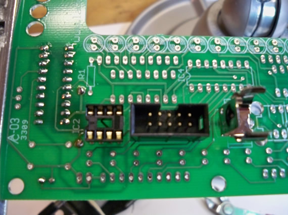
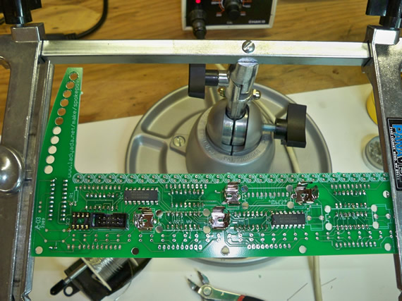
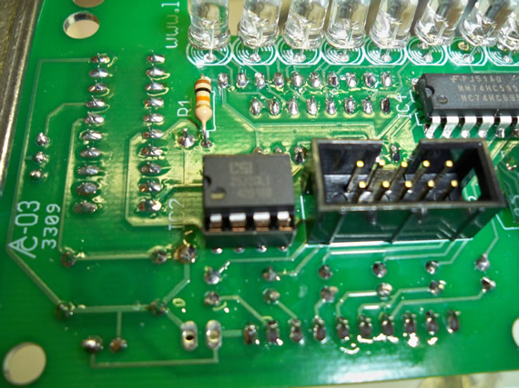
Here you can see the EEPROM chip socket and 10 pin ISP socket from the other side that I mention above.
It looks like all the IC latches that control the 60 LEDs have been installed. All but two of the latching ICs are on this side of the board.
These are the final two latching ICs on the other side of the PCB. Each latch will control up to 8 LEDs so you need a minimum of 4 latches per side. But being this is a double sided PCB it was designed with 6 latches on one side and 2 on the other. This is a good layout plan because you can then put all your battery clips on just one side of the board.
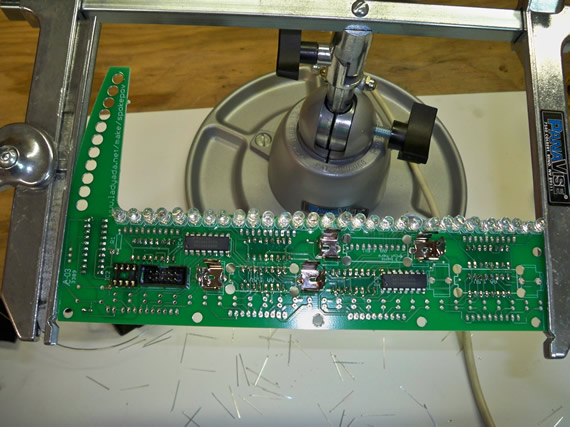
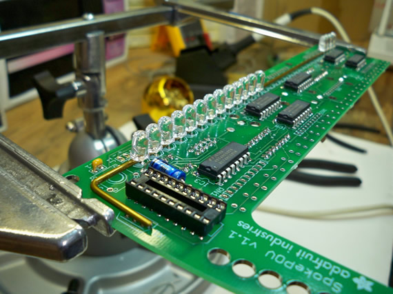
The LEDs are going in. She put in the LEDs from one side and then spread the legs so they stay put when she flips the board to solder and clip all the legs.
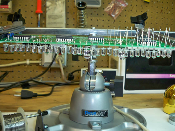
Later we realized it would have been better to flush mount the LEDs to the board so they don’t get bent back and forth as you mount and unmount the wheel.
All the LEDs are done on this side.
All the LEDs are now also done on the other side.
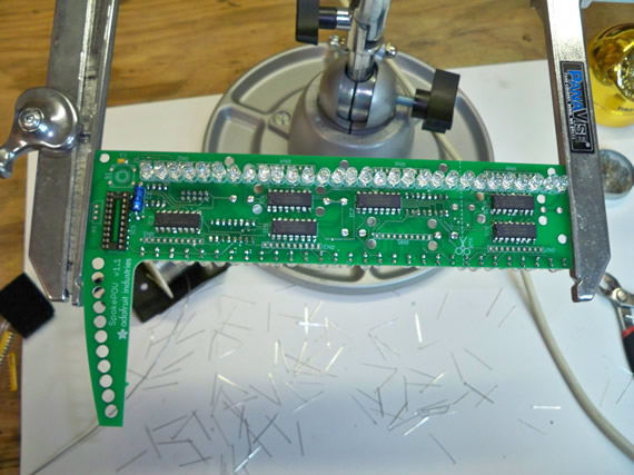
Here the yellow resistor packs are installed. These are a great component to use when you have a ton of identical resistors for a project. the restor packs save space on the PCB board compared to single resistors and WOW they save a ton of time if you’re building this kits by hand.
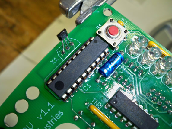
The combo red reset and power tectal button has been installed below.
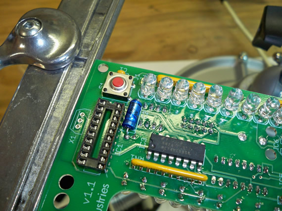
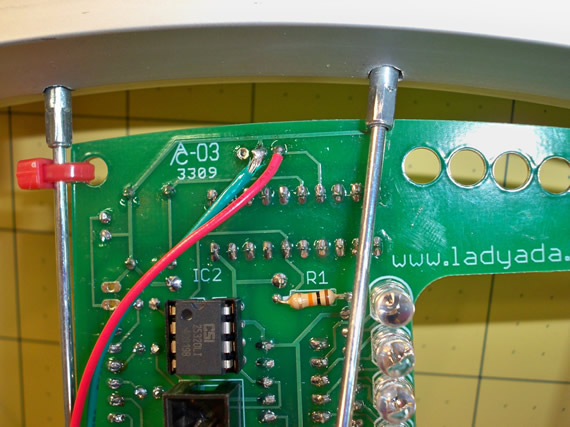
If you know what you’re looking at here you will see a small component soldered in at a silk screen marking “X1”. This is the hall-effect sensor that triggers each time the wheel rotates and passes by a magnet that will be installed in a stationary location on the bike frame. The MC uses this trigger to calculate the tire rotation speed so it can draw a sharp POV image at any given speed. Well, I say any speed but really if you only have one board the image will not look very solid at low speeds so we bought the 3 board kit and will later wire all 3 hall-effect PCB points to just this one hall-effect component. This board connection trick will allow all three boards to stay in perfect synchronization and draw a very solid image at even low speeds like 5 to 7 mph. This trick does require a little more wiring then documented in the official support website, which I elaborate on below and also requires each board to have it’s own rotational offset value which I document and calculate in a later blog.
Seen below is the 10k resistor installed from the EEPROM’s chip select (CS) pin to VCC.
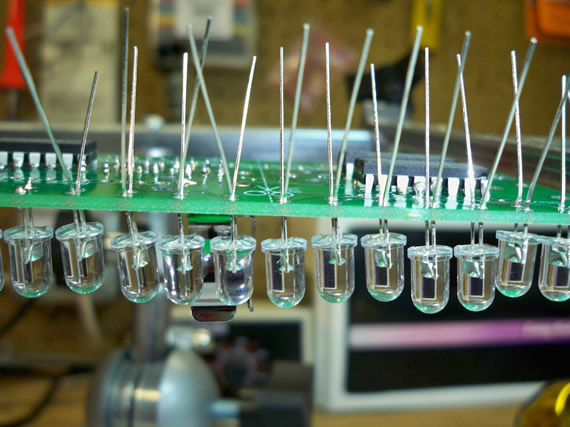
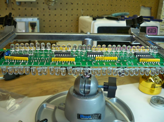
On to the 2nd board but seen below is a coat hanger wire under the LEDs to help control the height of each LED and keep them level. As mentioned before we realized only after all the boards were done that we should have flush mounted the LED in which case this coat hanger trick is not needed. PS, yes the coat hanger comes out after all the LEDs are mounted.
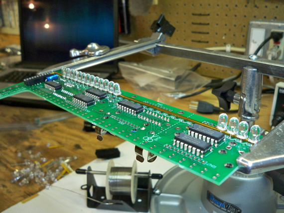
Another angle showing the coat hanger trick.
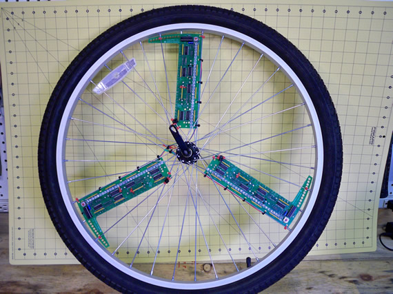
All three boards are done and zip tied to the spokes 120 degrees apart. But we wanted all three boards to fire simultaneously for each rotation to aid in POV animation running at 1 frame per rotation. If we leave the boards separate each board will fire correctly in space be the three boards will be displaying different animation frames at the same time and space making higher speed animation blurry. If you’re not doing animation or are doing very low frame rates like one frame per 10 rotations then this will not be much of an issue.
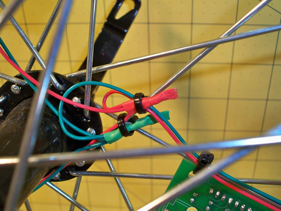
For us however we want quality fast animation so as hinted to above we wired the ground and sensor pins of each hall-effect point to just one hall-effect sensor. We did not install the other two hall-effect sensors on the other two boards because they are not needed and of course we didn’t wire the VCC pins of the hall-effect points together either. Pictured below is a green wire on the ground pin and a red wire on the sensor pin of the hall-effect sensor PCB point. We did this for each board running enough wire to get to the center of the hub.
We zip tied the hall-effect interconnect wires to the spoke mounts and ran these wires to the center of the hub. Yes we could have used the spokes as a ground line instead of running the extra green wire but the extra work guaranties we will not be troubleshooting functionality problems do to a bad ground signal through the spokes.
Here we soldered and mounted all red wires and all green wires together as well as zip tied them to a spoke near the center hub. Don’t forget the shrink wrap to keep the joints protected and looking nice.
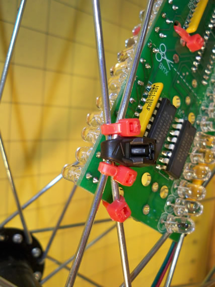
Before we fired up the boards for a test on the wheel we noticed that each board had one spot where some solder joints were shorting to a spoke.

Here we used extra zip ties as spacers to prevent any shorts between the boards and the spokes.
The final project is ready for testing. We wanted the programming and image testing to be easy which meant we didn’t want to be fighting with the bike when programming and testing. In the next blog I will document the build of a test rig that clamps into my bench vise and holds the wheel and a triggering magnet for easy testing and troubleshooting.

Links for Beginners in Electronics }:-)
Archives
- April 2017 (1)
- March 2017 (3)
- December 2016 (1)
- November 2016 (3)
- October 2016 (2)
- September 2016 (2)
- August 2016 (4)
- June 2016 (1)
- May 2016 (6)
- April 2016 (1)
- March 2016 (3)
- February 2016 (4)
- January 2016 (3)
- December 2015 (1)
- November 2015 (5)
- September 2015 (1)
- July 2015 (2)
- June 2015 (6)
- March 2015 (1)
- January 2015 (2)
- December 2014 (2)
- November 2014 (4)
- October 2014 (2)
- May 2014 (1)
- March 2014 (5)
- February 2014 (3)
- January 2014 (1)
- September 2013 (2)
- August 2013 (1)
- July 2013 (4)
- June 2013 (3)
- May 2013 (2)
- April 2013 (1)
- March 2013 (3)
- February 2013 (2)
- January 2013 (2)
- December 2012 (1)
- November 2012 (8)
- October 2012 (5)
- September 2012 (1)
- August 2012 (1)
- July 2012 (2)
- May 2012 (2)
- April 2012 (1)
- March 2012 (3)
- February 2012 (2)
- December 2011 (2)
- November 2011 (4)
- October 2011 (1)
- September 2011 (1)
- August 2011 (2)
- May 2011 (2)
- April 2011 (2)
- March 2011 (2)
- February 2011 (2)
- January 2011 (1)
- December 2010 (2)
- November 2010 (2)
- July 2010 (3)
- June 2010 (2)
- April 2010 (1)
- March 2010 (1)
- February 2010 (2)
- January 2010 (1)
- December 2009 (2)
- October 2009 (4)
- March 2009 (1)
- December 2008 (1)
- November 2008 (1)
- August 2008 (1)
- April 2008 (1)
- March 2008 (1)
- February 2008 (1)
- June 2007 (1)
- November 2005 (1)
- April 2005 (1)