
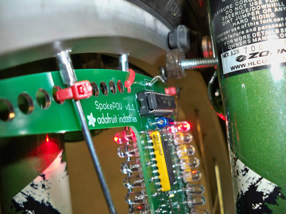
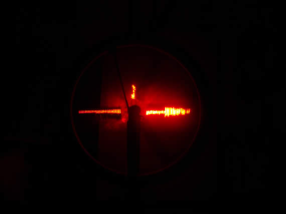
This is a continuing post in a series about using the Adafruit.com bicycle spoke persistence of view board (SpokePOV). This is a great electronics kit that lets you draw amazing images like below from LEDs attached to your bicycle spokes. You can even do animations while you ride if you use 3 SpokePOV boards which is also sold as a kit.

You may want to first read (part 1 of 7) of this blog post series.
I was going to post the next 5 parts separately but decided to just combine parts 2 through 6 in this posting. Below is the list and you can scroll to see each section. There maybe a final separate 7th posting on creating a “Corrective Raiser image Board” (CRiB) board to correct a slight design flaw with Adafruit’s SpokePOV boards as noted in part 6 below.
Part 2: Mounting an adjustable magnet on the bike frame
Part 3: Building bench testing rig for SpokePOV
Part 4: Programming images and setting the SpokePOV board offsets
Part 5: Halloween image and video of SpokePOV in action
Part 6: Troubleshooting an image skew problem
Part 2: Mounting an adjustable magnet on the bike frame
The SpokePOV kit comes with a very strong magnet which is used to trigger the Hall Effect sensor on the board as the board rotates with the wheel. In the suggested configuration from Adafruit the magnet just sticks to the inside of the bike’s front fork. This is not optimal because the magnet will not be adjustable with respect to the board and the magnet could easily fall off or move when encountering a bump. You could epoxy the magnet to the frame at a selected height but then the tire could be difficult to remove.
CLICK TO READ ALL —>:
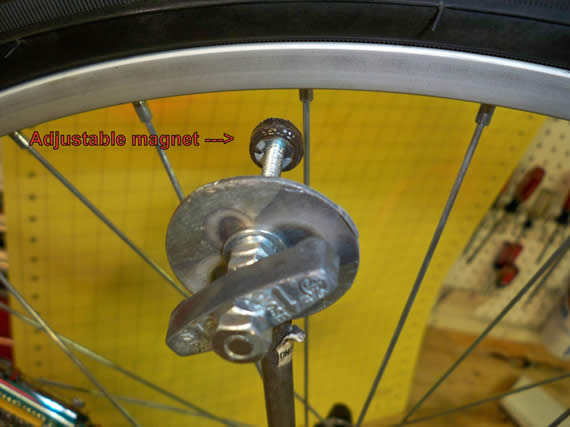
My solution was to drill a hole in the front fork brake caliber, epoxy a nut over the hole and then epoxy the magnet to the head of a bolt. I then cut the bolt to an exact length so that when it is screwed in with a locking washer under a makeshift handle it would tighten up just hovering over the Hall Effect sensor on the POV board. With this rig I can easily back off the magnet when I need to remove the tire and I would never lose my magnet or alignment. What follows in this section are photos of this magnet mount mod.
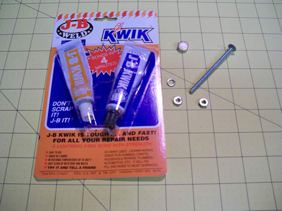
Supplies: J-B weld epoxy 4 minute bond, Thin bolt, two nuts and one locking washer.
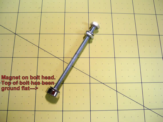
Grind the head of the bolt flat if it is not already flat.
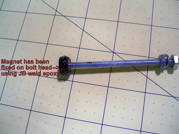
Epoxy the magnet to the head of the bolt.
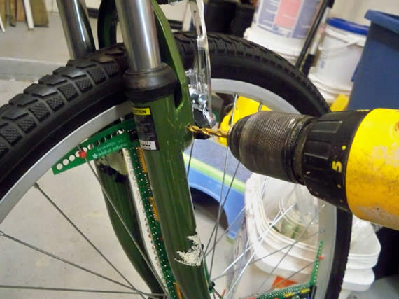
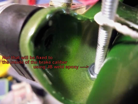
Drill a hole for the bolt through the brake caliber or other suitable part of the frame directly over the Hall Effect sensor on the POV board.
Put the nut over the hole on the inside of the fork. Use the bolt to keep it centered while you epoxy the nut in place.
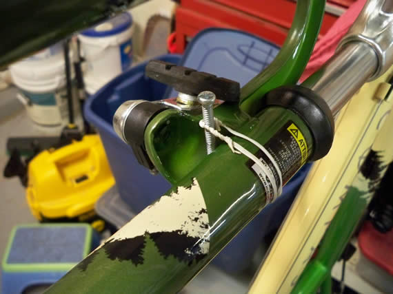
Use a wire or wire tie to keep the bolt in place while the epoxy dries.
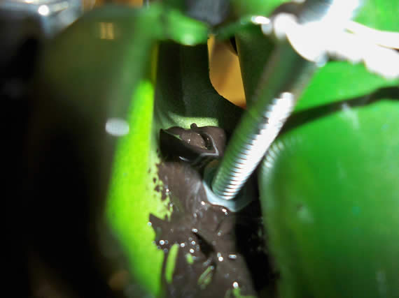
Put the 4 minute JB weld epoxy mix carefully around the nut. Don’t get any epoxy on the bolt or the inside of the nut. I used a tooth pick to carefully apply the epoxy.
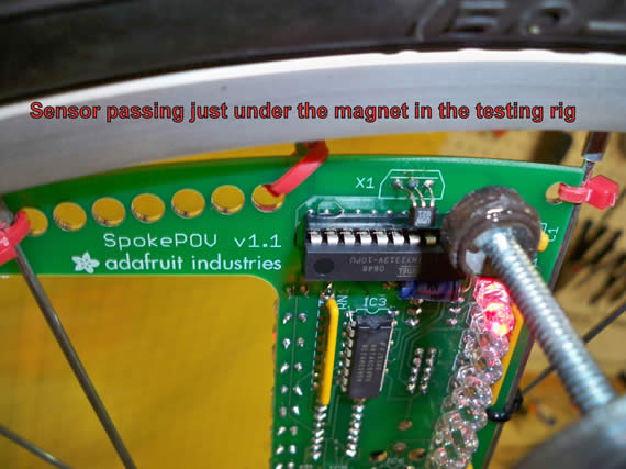
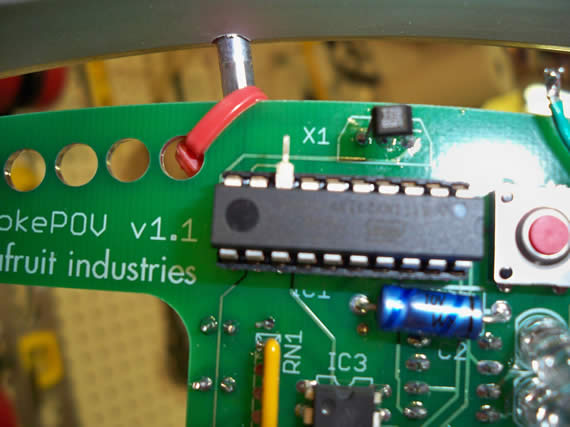
Once the 4 minute epoxy is dry you can tighten up the bolt with a 2nd nut and lock washer so that the magnet is just over the Hall Effect sensor by about a 1/4 inch or less. I created a makeshift handle out of an old handle and some additional nuts and lock washers. I wanted a handle so I didn’t need to get out tools to get the tire on and off being the magnet would otherwise be in the way.
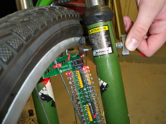
In this last photo you can see just how close I can set the magnet to the sensor on the POV board. This is best for getting a good clean Hall Effect trigger as the tire spins.
Part 3: Building bench testing rig for SpokePOV
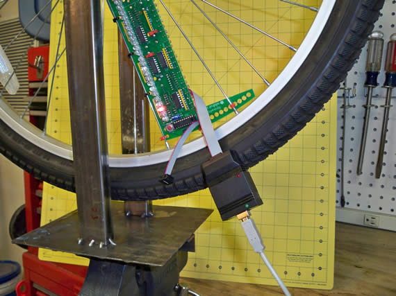
I wanted a simple test rig for my font tire when programming and testing new images. I absolutely hated having the bike upside down with the tire on it when trying to program and test. If the bike tipped over it would yank my programmer and maybe even my laptop to the floor. Plus the images would always be upside down.
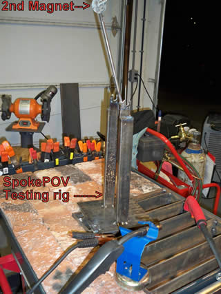
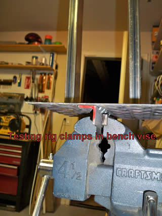
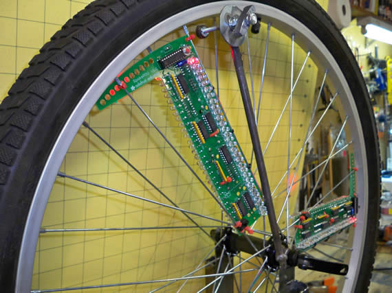
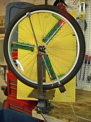
So I welded up this contraption in which I can quickly mount my tire and it securely clamps in my bench vise. The tricky part was adding the magnet to an extension rod welded to the test rig hub mount. It had to be welded at the same angle as my bicycle’s front fork with respect to the ground. You could build this out of wood just as easily but I have a welder so this was easy-peasy-lemon-squeezy for me. Here are some photos but you may want to also checkout my latest test rig that uses an old ceiling fan motor for the test rig.
There are some notes in the photos if that helps.
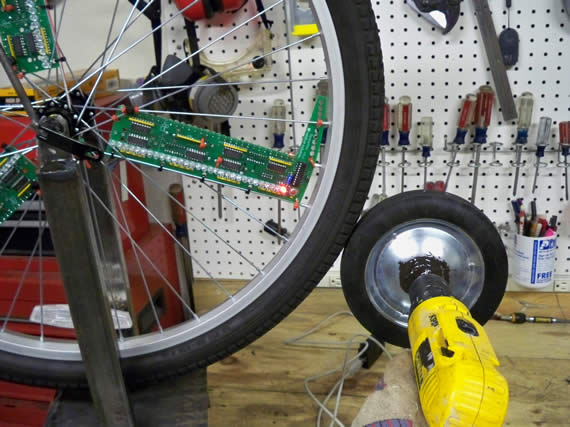
This is what I use to spin the tire. It is an old wagon wheel with the metal axel cut off. I epoxyed the wheel to the axel so that the drill could spin them both as one.
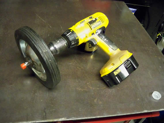
Set the drill on high speed and this gets the wheel going quite fast. Once again you may want to checkout my new ceiling fan motor test rig.
Part 4: Programming images and setting the SpokePOV board offsets
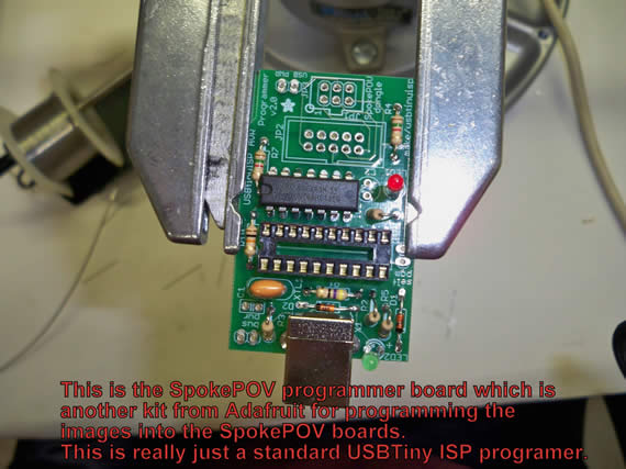
When I purchased my SpokePOV kit from Adafruit I also purchased their SpokePOV programmer kit. Really this I just their standard USBTiny ISP programmer with a named driver to make it simple for people that only use it to program a SpokePOV board. Turns out this is a very nice in-circuit programmer for programming many Atmega AVRs (click to see my posting on just such a project).
You do have to assemble your programmer kit but that’s what teenage daughters are for. Ha. This photo was taken during the assembly of the SpokePOV programmer.
The next step was to download and install the driver for your SpokePOV programmer and download the C++ software for image editing and programming. I recommend starting with a simple forward pointing arrow as your first image. You do have to connect the programmer to each board one at a time and load the same arrow image into each of the 4 banks on each board.
Make sure your programmer’s jumper is set to NOT provide power to the board, being the board should be self powered by batteries.
If you didn’t connect all three boards to the same Hall Effect sensor you are good to go, but if you want cleaner animation you should have connected the boards as I documented in part 1. With the boards linked all fire at the same time but each board is at a different location when they fire. This means that each board has to be programmed with a different image offset so all images overlay at the same exact location giving a super clean image at even low speed and with animation.
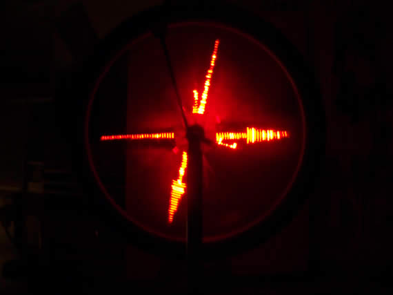
If your first image was a forward pointing arrow then setting the offset is simple. Label each board 1, 2 and 3 with a Sharpe. Start with only board 1 turned on and spin the wheel up to speed. Note the direction the arrow is pointing and calculate the offset needed to get the arrow to point forward. Stop the wheel, program this offset into board 1 and repeat until you get the arrow level and pointing forward.
PLEASE NOTE: in my photos there is a strange short vertical line perpendicular to my arrow. This is not intentional and seems to be related to a programming anomaly when writing the image to the boards memory banks. Sometimes this can be corrected by loading the image back from the board, erasing the erroneous pixels and re-uploading the image back to all 4 memory banks. This does not always fix this anomaly so I just live with it most of the time. (sad).
Next turn on both boards 1 and 2. When you spin up the wheel the 2nd board’s arrow image will be pointing in the wrong direction but board 1 will remain correct.
Once again calculate the offset needed to get board 2’s arrow to point forward. Stop the wheel, program board 2 with its new offset and repeat until both board 1’s image and board 2’s image are exactly lined up.

Repeat this process again for the 3rd board or as many remaining boards as you installed. The more boards you have the better your images and animations will be at low speeds. Write the offset on each board so you don’t have to repeat this process if the chip’s offset somehow get reset.
Part 5: Halloween image and video of SpokePOV in action
This is my daughter’s bike and she likes to program in an image for each season. Here she put up a pumpkin image she downloaded. (sorry I lost the link ). She has also done Christmas trees and so on and so forth. Lots of fun and a bit of added safety when riding at night.
Sorry but my camera does not do a very good job of recording. The images do look a ton better live.
Part 6: Troubleshooting an image skew problem
We noticed a perplexing issue with our images. The left side of the wheel, from the passengers view point, had a skewed image. The image forward of the hub was high by about 1.5 inches while the image behind the hub’s center point was low by 1.5 inches. However the image on the right side of the wheel looked just fine. This became very apparent if you wanted to display an arrow passing through the center of the hub on the left side or any other image passing through the hub.
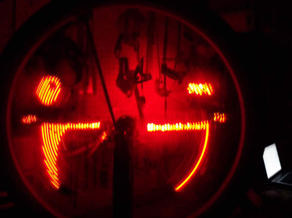
This is a smiling face with winking animated eye on the right side which always looks good:
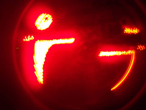
This is the left side that is always skewed. Notice how the smile is high on one side and low in the other:
It actually turns out to be a mounting geometry issue which is unavoidable because of the layout of the LED’s on the board. The old “round peg in a square hole” issue. It took me one of those “I should have had a V8” moments to finally grasp what was going wrong. What follows is my troubleshooting approach and detailed conclusions and solutions.
Troubleshooting steps, detailed conclusions and solutions
I started my troubleshooting by turning on just one POV board but I had the same problem as I did with all three boards sharing a single sensor. I reinstalled the sensors on all three boards and each board had the same problem independent of the other boards.
I was convinced it was firmware so I downloaded the “C++” source code from Adafruit and started going through that but nothing jumped out at me as being a code issue between how the left and right side of the wheel was controlled.
I started examining the circuit schematic. It appeared to me that the latch select lines between the left and right side of the wheel maybe shorted or somehow crossed causing them to fire as if they were one side. I took out the micro controller chip and started tracing the 12 pins on all latch chips. But my digital multi meter said the two sides were not crossed physically so that wasn’t the problem.
Some brute force troubleshooting was in order. I pulled out the micro controller again and bent out pin 9 (“The left side select pin” on schematic) and re-inserted the chip.
Without pin 9 connected nothing was controlling the left side of the wheel so it was dark and as expected only the right side was on and the image looked good. I then repeated this test but this time I removed pin 8 (“The right side select pin” on schematic) and reconnected pin 9.
Now only the left side had lights on and the image was skewed as before with half the image high and the other half low.
I next bent out both pins 8 and 9 on the micro controller but I also crossed pin 9 to the connection point on the PCB where pin 8 would normally be connected. See the small U shapped jumper wire solderd in this photo near the spoke on the PCB.
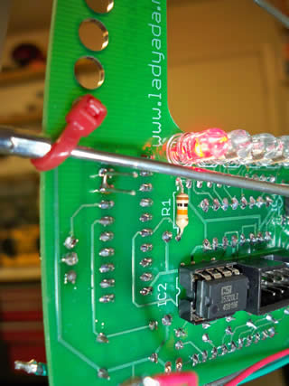
At this point I would have expected only the right side to have lights and for the image to be skewed as it was when this pin controlled the left side. But that didn’t happen. The image was on the right true enough but the image looked just fine, not skewed at all. How could this be? If the problem was a firmware issue or other timing issue then pin 9 controlling pin 8’s side should have the same problem but it didn’t. The problem just seemed to evaporate.
I sat for a while just looking at the wheel and how the boards were mounted and then eureka! The problem now made complete sense. The board is square and the wheel is round! That can’t work because only one row of lights on one side can be pointing at the center of the hub which means the other side will always be skewed as it is drawing thinking the center of the wheel is in a different location than it really is.
I had mounted the boards flat on just one side of the wheel along one of the spokes. The boards are square and the lights on one side are aligned along the spoke therefore only one row of lights on one side can be pointed at the center hub.
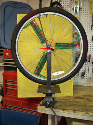
Below is a photo of the good side where the LEDs line up almost perfect with the hub.
I drew in red lines to extend the line of LEDs through the center hub.
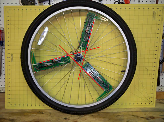
Below is a photo of the bad side where the offset of LEDs on the back side of the board are skewed off to the side of the center hub. Once again I drew in red lines to extend the line of LEDs skewed to the side of the hub.
This install method forces the lights on one side of the board to be pointed radial at the center hub leaving the other side’s row of lights skewed and NOT pointing at the center of the hub. I zip tied one edge of the PCB along one spoke and since my bike has a very small center hub ring for the spokes to connect to the problem was exaggerated over other bikes that have a larger center hub spoke ring.
This is an unavoidable side effect of the board layout and at best you can mount the boards NOT following a spoke and splitting the difference so that each side is slightly skewed but not as dramatically as it would be if you centered just one side of lights with the hub as I did. I guess one could also put the boards in the center of the spokes between the left and right side of the wheel and put a twist in the bottom of the board closest to the hub helping each row of lights on each side point a bit closer to the center of the hub but what a fuss.
A triangle shaped PCB board may have been a better design choice and would have allowed the LEDs on both sides to fall along a true radial line with the hub. Maybe this is a good idea for v2.0 perhaps.
I’m not sure this alignment issue can be corrected in the software or not. It would be more of a Hubble Telescope corrective surgery then anything else. Maybe the user could be instructed to measure the offset between the hub and the row of LEDs on each side of the board allowing the software to introduce some corrective timing. If anybody wants to tackle this corrective surgery of the firmware I’m sure all users of this board version would be greatly appreciative! Drop me a line if this ever comes to fruition.
For now my solution to this problem is going to be a pricy one. I plan on just cutting the 9 pin on each micro controller for all three boards so the LEDs on the left inside are off. Then I will get another 3 boards for the other side cutting the 8 pins or just not soldering on the right side components. I will wire all 6 boards to a single sensor, have the outward facing LEDs 100% inline with the center hub and each board will have its own rotational offset. This will create perfect animation on either side at all speeds.
Wait! I have a cheaper solution then buying 3 more boards but it will take some design time first. I could create a raiser board that bolts to the current SpokePOV board inline with the right side LEDs but on the opposite side of the board. I can then move all the left side LEDs to this new raiser board. Then both sides will have a line of LEDs 100% inline with the center hub.
I may have to design the board so the 4 latches also move to the raiser just to keep the wiring between the two boards at a minimum.
When I’m done with the raiser board design I will post the files alone with SpokePOV board modifications, wiring and mounting instructions. Others can then etch and mount their own “Corrective Raiser image Board” (I think I will call it the CRiB board).

Links for Beginners in Electronics }:-)
Archives
- April 2017 (1)
- March 2017 (3)
- December 2016 (1)
- November 2016 (3)
- October 2016 (2)
- September 2016 (2)
- August 2016 (4)
- June 2016 (1)
- May 2016 (6)
- April 2016 (1)
- March 2016 (3)
- February 2016 (4)
- January 2016 (3)
- December 2015 (1)
- November 2015 (5)
- September 2015 (1)
- July 2015 (2)
- June 2015 (6)
- March 2015 (1)
- January 2015 (2)
- December 2014 (2)
- November 2014 (4)
- October 2014 (2)
- May 2014 (1)
- March 2014 (5)
- February 2014 (3)
- January 2014 (1)
- September 2013 (2)
- August 2013 (1)
- July 2013 (4)
- June 2013 (3)
- May 2013 (2)
- April 2013 (1)
- March 2013 (3)
- February 2013 (2)
- January 2013 (2)
- December 2012 (1)
- November 2012 (8)
- October 2012 (5)
- September 2012 (1)
- August 2012 (1)
- July 2012 (2)
- May 2012 (2)
- April 2012 (1)
- March 2012 (3)
- February 2012 (2)
- December 2011 (2)
- November 2011 (4)
- October 2011 (1)
- September 2011 (1)
- August 2011 (2)
- May 2011 (2)
- April 2011 (2)
- March 2011 (2)
- February 2011 (2)
- January 2011 (1)
- December 2010 (2)
- November 2010 (2)
- July 2010 (3)
- June 2010 (2)
- April 2010 (1)
- March 2010 (1)
- February 2010 (2)
- January 2010 (1)
- December 2009 (2)
- October 2009 (4)
- March 2009 (1)
- December 2008 (1)
- November 2008 (1)
- August 2008 (1)
- April 2008 (1)
- March 2008 (1)
- February 2008 (1)
- June 2007 (1)
- November 2005 (1)
- April 2005 (1)