
Part1:
In this blog posting I’m attempting to diagnose a problem with a motor power supply for a small metal lathe. I will document how I evaluate a circuit board and repair it if possible.

I’m confident the problem is with the power supply because when I plugged in the lathe nothing happened. The motor doesn’t flinch even when the speed control is turned to high. Plus there is no voltage at all across the motor terminals so that does make sense. Something in the motors power supply is preventing power getting to the motor terminals.
There are always a few steps I take when attempting to repair something electrical.
READ —>:
But first: “Is it safe to work on?” Power supplies that run off mains are always dangerous to work on because you’re going to be exposed to deadly voltages. Mains are 110-120v AC in the US and 220-240v AC in most other countries. Anything over 36v is technically dangerous because your salty fluid filled body is a really good conductor at voltages much higher than 36v. If you’re not experienced working around high voltage then PLEASE keep your repair efforts to circuits powered by 24v or less.
You have been WARNED! Plus most power supplies can be replaced for $30 to $60 dollars and aren’t worth the time or effort to repair let alone risk your life repairing.
Check that you have AC at the outlet. I know this seems like a stupid simple step but trust me, I have helped so many people fix an electrical problem with an appliance simply by flipping a circuit breaker.
Next check: When the device is plugged in and not working is there any smoke, flames or smells of burning electrical damage? If so unplug it and throw it in the trash. Just kidding, you might still be able to repair it but fire tends to cause extensive damage to a circuit board and I don’t know about you but having a fire hazard in my house causes insomnia.
Check to make sure any cooling fans are spinning up at full speed. A stuck or failing fan can cause the circuits to overheat which in turn can trip or blow a fuse or cause a thermal fuse to shutdown the unit until it cools. You will know if a thermal fuse has tripping if letting the device cool down for an hour brings it back to life for a spell.
The next step is to unplug and disassemble the power supply so we can get a good look at all the bits inside. Safety Step: some capacitors can hold a large charge and sometimes at quite high voltages so use a screwdriver to short across large capacitor leads. If you don’t like the loud SNAP of the discharge you can use a low ohm high wattage resistor for a 5 count.
I always start my scan of the board looking for a fuse. Sometime this is a resettable fuse and other times it’s just the kind that goes POP. Sometimes the fuse is hidden inside a covered compartment where the power plug connects. When you find it test it for continuity using a Multimeter. If it’s no good you can replace it and your back up and running…unless something mores serious caused the fuse to blow.
As noted before, poor running cooling fans could cause the fuse to trip so replacing the fans and fuses may complete the repair.
I was not so lucky. My power supply had no fans and the fuse was fine.
My next step is to scan the board top and bottom with my eyes looking for obvious damage. I’m looking for burnt spots, popped capacitors, fizzled resistors or transistors and damaged circuit board traces. Really you’re looking for any damage. If you’re lucky and can find physical damage and can still decipher the labeling on the parts your fastest repair option is to unsolder the damage bits and replace them with identical parts. However, if you can’t read the labeling you could try to find and examine an undamaged product or see if anybody posted a photo or schematic online. I once fixed an Xbox power supply after finding some hi-res photos and schematic other hacks had posted online, SCORE!
I couldn’t find any such damage with my board so I repeat the above scan with my nose. Yes! I said my nose. Your nose can pickup the slightest smell of electrical damage that your eyes can’t see. I have found many problems on circuit boards with my nose. The exact damaged component may not be obvious right away but you can test the components quickly in the area that smells. Once the defective parts are replaced you might be all fixed up.
No smelly smells on my board so onto the next step. I got out my Multimeter, set it on diode test and started checking a few target components. You can’t always check components in circuit but you can make a quick list of components to test if they don’t pass in circuit. Knowing what components to target for an in circuit test and how to test is kind of an art skill one develops over years of poking around with board repair along with a solid background in electrical circuit theory. I know most people don’t have such skills but you can still take a whack at testing the diodes and transistors. Your meter should show if a diode passes the forward test and should show open-loop OL in reverse, but not always in circuit of course. A lot of transistors “in circuit” will pass a forward diode test between two leads and show OL when reversed. This by no means is a guaranty test but if the components pass you can “most likely” focus your trouble shooting attention elsewhere for now. Of course if you still suspect a device you can unsolder it and test it out of circuit, but I don’t recommend going there until after you have eliminated other possibilities.
I couldn’t find any discrete components that seemed defective so I had to move on to looking at non-discrete components like ICs “integrated circuits”. These are what a lot of people call chips. Chips can be simple ICs with just a few simple circuits inside sharing a common package but not really internally connected. Other ICs will be complicated microprocessor or CPUs with countless internally connected components and circuits. At this point you’re really almost out of luck unless you have the original circuit diagram and in the case of a microprocessors a pin-out diagram including the programmed functionality of the micro. Unless you’re working on a known product, product you designed or open source hardware you’re not going to be privy to that information. The best you can hope for is probing around with a good oscilloscope looking for anomalies. Maybe you will find a trace that you can tell needs a signal for functionality but one doesn’t exist and you can source it back to a defective IC that doesn’t require any kind of programming or perhaps the IC appears to not be getting power or is not getting a required feed signal of its own.
Well here is where I hit a little pay dirt. I could tell the power transistors for the motor where not getting a gate signal to turn them on and the gates traced right back to an IC’s output control pin. Something was wrong with the IC or its power or its own feed signals. But to continue I need to know what is inside this IC and other ICs on the board as well as details on the power transistors.
I needed datasheets. First I jot down the transistor and IC labels then I plug them into www.findchips.com which gives a listing of suppliers who in turn link to datasheets. With the datasheets I know the pin-outs, functionality and sometimes even example circuits matching what I see in my circuit.
Wow, datasheets are a goldmine if you know how to sift out the real nuggets of information you need. If you’re new to datasheets maybe this will help: How to Read a Datasheet
Here is some of the needed details on my transistors and ICs:
BC337N
TRANSISTOR
NPN
TO-92
DC Collector Current:800mA
Collector Emitter Voltage V(br)ceo:45V
Power Dissipation Pd:625mW
DC Current Gain Max (hfe):630
Transition Frequency Typ ft:210MHz
Datasheet

BC327N
TRANSISTOR
PNP
TO-92
DC Collector Current:800mA
Collector Emitter Voltage V(br)ceo:45V
Power Dissipation Pd:625mW
Transition Frequency Typ ft:100MHz
DC Current Gain Max (hfe):100
Datasheet
LM324N
Quad operational amplifiers
IC OP AMP LP QUAD 14-DIP
Datasheet
Buy

UC3843N
CURRENT MODE PWM CONTROL
Datasheet
Buy

LM339N
Quad voltage comparator
IC COMPARATOR LP QUAD 14-DIP
Datasheet
Buy

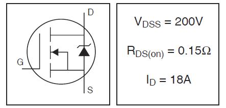
IRF640
Power Transistor
MOSFET N-CH 200V 18A TO-220
Datasheet
Buy

The smallest chip, UC3843N, is a “CURRENT MODE PWM CONTROL”.
This chip’s output on pin 6 controls the two big IRF640 power transistors.
These power transistors are “MOSFET N-CH 200V 18A TO-220”

The power transistor’s job is to supply power to the motor when pulsed ‘ON’ by the PWM controller. There are two of these transistors in parallel only because one would get too hot at peak current. Instead of getting a more expense power transistor to handler the current load the designer just ganged two cheaper grade ones in parallel. I’ve done the same myself for projects. This is cheap, fast and uses what you have on hand. That said, there is a lot of sad corner cutting to this power supply design, but I have to hand it to them for making it work.
The yellow do-dad on the back of the motor is just a coil with a magnet inside that spins with the motor’s shaft. This then sends pulses back to the circuit board which is picked up as feedback and used to control the speed of the motor via the above PWM controller.

And of course you can select the speed using this pot which is being sampled.

As of now I’m sure the power transistors are fine. The fuse is good and the power rectifiers also seem ok. Power is being supply to the board, but I’m not sure its the right voltage values yet and a little off could be causing big problems. They are using some crazy tricks to get the values they need, but if the values turn out to be there then it should be fine. Dirty, doable and done seems to be the designers approach with this power supply.

I stopped tracing the problem tonight at the PWM controller’s pin 6. It was not pulsing! This could mean the chip is bad or that something feeding into the PWM controller is bad.
I should have more time for this repair Wednesday night or this weekend. Check back later for a new post titled “Part 2“.
Todd

Links for Beginners in Electronics }:-)
Archives
- April 2017 (1)
- March 2017 (3)
- December 2016 (1)
- November 2016 (3)
- October 2016 (2)
- September 2016 (2)
- August 2016 (4)
- June 2016 (1)
- May 2016 (6)
- April 2016 (1)
- March 2016 (3)
- February 2016 (4)
- January 2016 (3)
- December 2015 (1)
- November 2015 (5)
- September 2015 (1)
- July 2015 (2)
- June 2015 (6)
- March 2015 (1)
- January 2015 (2)
- December 2014 (2)
- November 2014 (4)
- October 2014 (2)
- May 2014 (1)
- March 2014 (5)
- February 2014 (3)
- January 2014 (1)
- September 2013 (2)
- August 2013 (1)
- July 2013 (4)
- June 2013 (3)
- May 2013 (2)
- April 2013 (1)
- March 2013 (3)
- February 2013 (2)
- January 2013 (2)
- December 2012 (1)
- November 2012 (8)
- October 2012 (5)
- September 2012 (1)
- August 2012 (1)
- July 2012 (2)
- May 2012 (2)
- April 2012 (1)
- March 2012 (3)
- February 2012 (2)
- December 2011 (2)
- November 2011 (4)
- October 2011 (1)
- September 2011 (1)
- August 2011 (2)
- May 2011 (2)
- April 2011 (2)
- March 2011 (2)
- February 2011 (2)
- January 2011 (1)
- December 2010 (2)
- November 2010 (2)
- July 2010 (3)
- June 2010 (2)
- April 2010 (1)
- March 2010 (1)
- February 2010 (2)
- January 2010 (1)
- December 2009 (2)
- October 2009 (4)
- March 2009 (1)
- December 2008 (1)
- November 2008 (1)
- August 2008 (1)
- April 2008 (1)
- March 2008 (1)
- February 2008 (1)
- June 2007 (1)
- November 2005 (1)
- April 2005 (1)