Part2:
I’m attempting to diagnose a problem with the motor power supply for a small metal lathe. This is part 2 so you may want to read part 1 first.
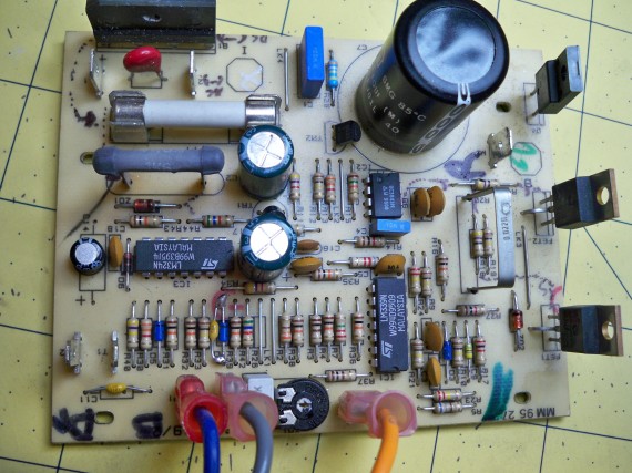
I know the 120v AC mains are flowing through a monolith bridge rectifier and coming out as a fully rectified pulsing DC signal. This rectified DC signal is smoothed out by a very large 220v 300uF cap which is then supplying “somewhat clean” DC to the (+) terminal on the motor. Notice I didn’t say anything about a transformer because there isn’t one. That means the voltage to the motor is not being stepped down; just full wave rectified and smoothed out with a large cap.
READ —>:
Even stranger I trace all the Vcc pins on the ICs back to an un-rectified 120v AC main! However, the trace does go through a big fat 1800 ohm 4watt resistor and then a large smoothing cap. Also the IC ground pins all trace back to the rectified 0v DC trace. For now I’m going to assume this is providing something close to the max voltage my ICs can handle per the datasheets 32v. I will test this later but I would say it for sure it will not be a nice stable clean Vcc supply.
Two IRF640 power transistors provide a path to ground for the motor when their gates are energized. The gates are controlled by a UC3842 current mode pulse width modulation chip (PWM). The duty cycle of the PWM is controlled by other components which will be discussed later.
If the PWM duty cycle is set to 0% there will be no on/off pulses to the power transistor gates hence the power transistors will never turn on hence the lathe motor gets 0V and will not run. At the other extreme, if the PWM duty cycle is 100% the motor will get continues DC and would run at full speed. When the PWM duty cycle is somewhere between 0% and 100% the motor will receive DC power for only a portion of time relative to the duty cycle.
Being these on/offs signals to the motor’s power supply are very fast the motor behaves as if it was being powered continually at a lower voltage relative to the PWM duty cycle. The lower the perceived voltage the slow the motor will run. The lathe’s motor is only rated for 90v DC continues so the UC3842 will never be allowed to go over a given duty cycle thus protecting the DC motor from being over powered. Of course the duty cycle can be dialed down to run the motor slower than its maximum speed.
I’m now at the point where I really need to know just how the transistors and ICs are working together. I do this by tracing out some of the circuit and mapping out a portion of a circuit diagram. If you’re lucky like me you will have a single sided PCB board. This means the copper traces are all on one side and the components are on the other side. If you have a double or multilayered PCB then you might not be able to trace out much of the circuit and the board is probable not going to be serviceable anyway.
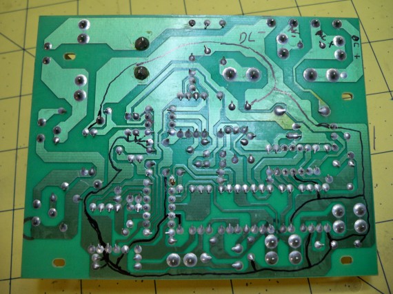
In the below photo you see I first highlighted all the ground traces in black.
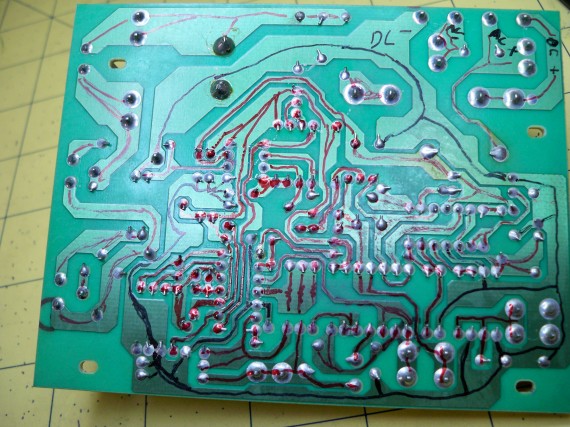
Then in the next photo I mapped out select traces to select ICs and transistors in red. I normally do just enough of this to get an understanding of what part of the ICs are being used and what transistors, resistors, caps ect. maybe involved. But for this demonstration I painstakingly traced everything marking traces in red as they were added to my circuit diagram on paper.
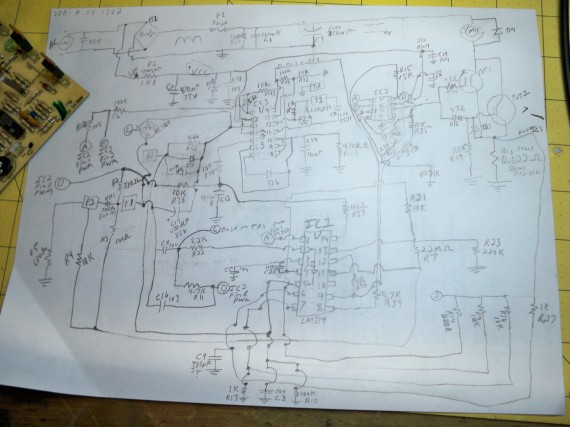
A complete circuit diagram is a huge help in trouble shooting a board but really I just need the circuit diagram for select pins on select ICs to proceed with the diagnostics. Here is a hi-res shot of the hand sketched circuit diagram. It was way too much work but kind of fun in an obsessive compulsive way.
(click photo for hi-res)
I will most likely take some time to redraw this diagram on several sheets of engineering paper for further reference in a cleaner layout, but truthfully that’s not needed.
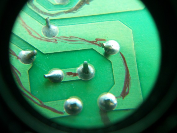
During the tracing process I did notice the below dry solder joint on a signal line to a power transistor but it electrically tested fine. I took the photo with a couple of eye piece loupes which is why it looks so funny. But this trick makes for super close up shots with a cheap point-n-shot camera.
I don’t have time for anymore tonight nor do I have time to work on this project for a few days. Most likely I will get time next week to tackle some more of this project and upload part 3.

