
19th March
2011
I’m trying something new. This posting will be a video blog posting. All the content is in the video. I’m limited to 15 minute videos on YouTube so I had to split the content into two clips (1a & 1b).
It is be kind of a trouble shooting tutorial slash what am I trying next video. I will also post some photos and links as normal but let me know if you like the video format better. I know the camera and sound sucks but I have to use the equipment I have which is a 15 year old Sony digital 8 Handycam with built-in mic. Sad I know.
After the videos are some oscilloscope screen shots of some test points and what they mean.
(video)
(oscilloscope screen shots
Key:
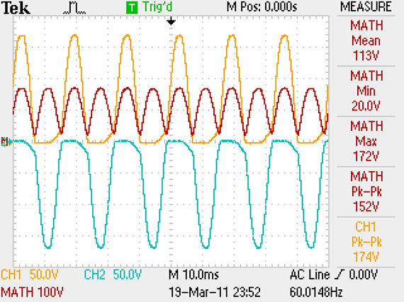
yellow trace: ch1 (+ test point)
blue trace: ch2 (ground plane at rectifier)
red trace: (ch1 – ch2)
Key:
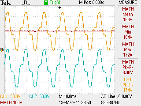
yellow trace: ch1 (+ test point)
blue trace: ch2 (ground plane at rectifier)
red trace: (ch1 – ch2)
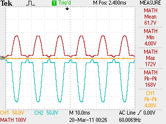
((This first screen shot is the signal across the bridge rectifier showing full rectification as the 152v peek-to-peek (20v to 172v) pulsing DC red trace. The math is displayed on the right for the red trace. I disconnected the bridge rectifier from the circuit so no filter caps are present to smooth out the dc pulses.))
READ —>:
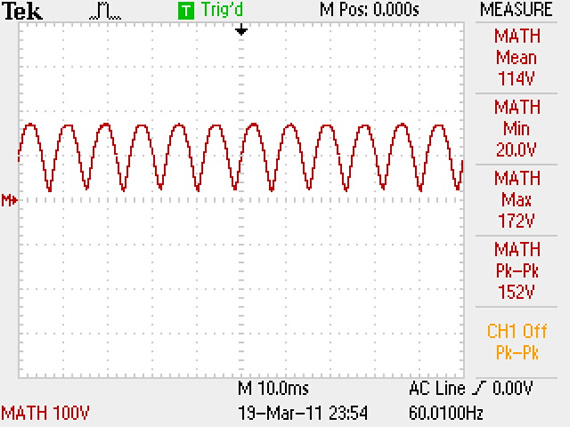
((Same but with ch1 and ch2 hidden.))
((Below shows the bridge rectifier has been connected to the circuit so the large smoothing cap has removed the pulses on the red trace leaving just the 170v DC signal which is used by the motor only.))
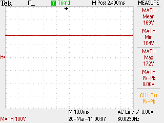
((Same but with ch1 and ch2 hidden.))
((Below is the half-wave rectified signal at the bridge rectifier for the power to the chips. Once again it is not connected to the circuit so no inline attenuating resistors or soothing caps yet so we see 176v peek-to-peek DC pulses (~0v to ~176v DC pulses). Being this is half-wave rectified the math averages the DC pules to 56.2v for Mean DC.))
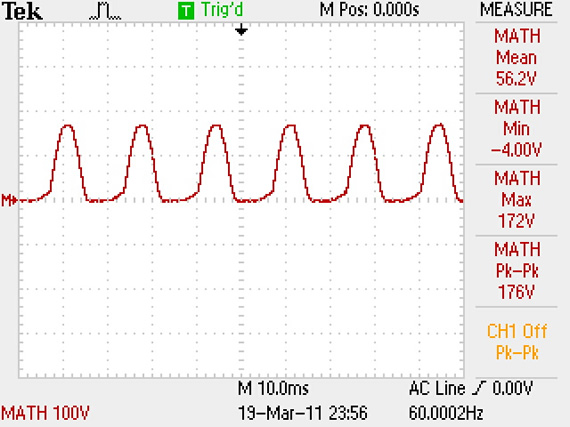
((Below screen shot is with the rectifier in the circuit but still probing at the rectifier. This is half-wave rectification still because Ch1 “yellow” is still connect to what is the common leg of the 120v AC going to the bridge rectifier. The scope reads this point as chassis ground. This is the point that is used to feed the half-wave rectification power to the IC’s.))
((In the next screen shot the ch1 probe “yellow” has been moved to the Vcc of one of the ICs. This test point is after a 1.8k 4watt inline voltage attenuating resistor and some smoothing caps. That is why you don’t see the half-wave pulses anymore and why the math is showing 16.3 volts DC as the red trace. There is a lot of ripple (8.00v peek-to-peek) riding on this 16.3v DC signal per the math on the right. ))
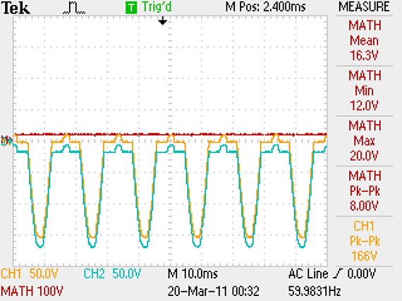
This calculated 8v ripple could be causing me some issues but really I think this is just noise that the chassis of the scope is picking up from the mains and is not really part of the voltage signals at the ICs. I might have been able to turn on my bandwidth limit on my scope and removed the noise if it really was just high frequency noise. It is hard to tell when using two probes in differencing mode and at such high line voltages.
In the up coming (part 5) I will be powering just the ICs side of the circuit with a bench power supply at ~16v to see if a cleaner signal fixes the problem. But if not it will give me the freedom to safely probe about the board while I track down the problem. I’m glad I only do this for fun. I would starve to death if my paycheck relied on my ability to fix powers supplies. Ha.
Just posted part 5.

Links for Beginners in Electronics }:-)
Archives
- April 2017 (1)
- March 2017 (3)
- December 2016 (1)
- November 2016 (3)
- October 2016 (2)
- September 2016 (2)
- August 2016 (4)
- June 2016 (1)
- May 2016 (6)
- April 2016 (1)
- March 2016 (3)
- February 2016 (4)
- January 2016 (3)
- December 2015 (1)
- November 2015 (5)
- September 2015 (1)
- July 2015 (2)
- June 2015 (6)
- March 2015 (1)
- January 2015 (2)
- December 2014 (2)
- November 2014 (4)
- October 2014 (2)
- May 2014 (1)
- March 2014 (5)
- February 2014 (3)
- January 2014 (1)
- September 2013 (2)
- August 2013 (1)
- July 2013 (4)
- June 2013 (3)
- May 2013 (2)
- April 2013 (1)
- March 2013 (3)
- February 2013 (2)
- January 2013 (2)
- December 2012 (1)
- November 2012 (8)
- October 2012 (5)
- September 2012 (1)
- August 2012 (1)
- July 2012 (2)
- May 2012 (2)
- April 2012 (1)
- March 2012 (3)
- February 2012 (2)
- December 2011 (2)
- November 2011 (4)
- October 2011 (1)
- September 2011 (1)
- August 2011 (2)
- May 2011 (2)
- April 2011 (2)
- March 2011 (2)
- February 2011 (2)
- January 2011 (1)
- December 2010 (2)
- November 2010 (2)
- July 2010 (3)
- June 2010 (2)
- April 2010 (1)
- March 2010 (1)
- February 2010 (2)
- January 2010 (1)
- December 2009 (2)
- October 2009 (4)
- March 2009 (1)
- December 2008 (1)
- November 2008 (1)
- August 2008 (1)
- April 2008 (1)
- March 2008 (1)
- February 2008 (1)
- June 2007 (1)
- November 2005 (1)
- April 2005 (1)