
Search results for "arduino"
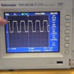
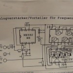
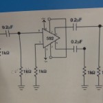
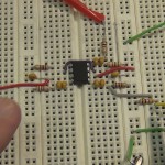
This is (PART 2A & 2B) of the project “Arduino Frequency Display For a Kenwood TS-520S HF Ham Radio”. This part covers small signal amplification of a 0.2 volt peak-to-peak 5.5 MHz signal into Schmitt triggered NAND gate for cleanup before being cleanly counted by the Arduino. Links to all parts: (PART 1), (PART 2), (PART 3), (PART 4), (PART 5)
(PART 2A)
(PART 2B)
Here are the datasheets for the two chips I used in (PART 2)
74HCT132 Quad 2-input NAND Schmitt trigger (PDF)
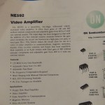
NE592 video Amplifier (PDF)
Thanks for joining!
Photo Gallery
CLICK PHOTO for gallery view and click a SECOND time for hi-resolution image. Click thumbnails on lower right and lower left of gallery to navigate gallery photos.
Thanks for joining!
This is (PART 1). Links to all parts: (PART 1), (PART 2), (PART 3), (PART 4), (PART 5)
A friend has a Kenwood TS-520S HF (high frequency) ham radio. He does not have the optional DG-5 frequency display and calibrating the dials between bands is not much fun. He gave me some information about the DG-5 and through some review I believe I can make a substitute for the DG-5 using an Arduino, LCD Shield and hand full of chips.
He could buy a DG-5 but that would cost more than he paid for the whole rig and it really is not necessary to use the radio, just more convenient.
This is part one so watch this video which covers my idea and some pre-testing. All looks good so far and I’m already working on part two.
I got the Arduino frequency library from this site:
http://interface.khm.de/index.php/lab/experiments/arduino-frequency-counter-library/
In the video I just use the library example scketch so I have no code to share in part 1.
I also followed some circuit examples shared at these two sites which both built HF frequency counts and were great sources of information to help me on my way to building an Arduino derivative HF frequency counter. My counter is for a single custom application and so doesn’t incorporate all the features these other builds include.
http://aade.com/DFD2inst/DFD2inst.htm
http://www.avr-asm-tutorial.net/avr_en/fcount/fcount_m8.html
Arduino website to get development software and sample code:
I got my Arduino and LCD shield from Adafruit.com
http://www.adafruit.com/products/50
http://www.adafruit.com/products/714
Some chips and data sheets I have used in part one:
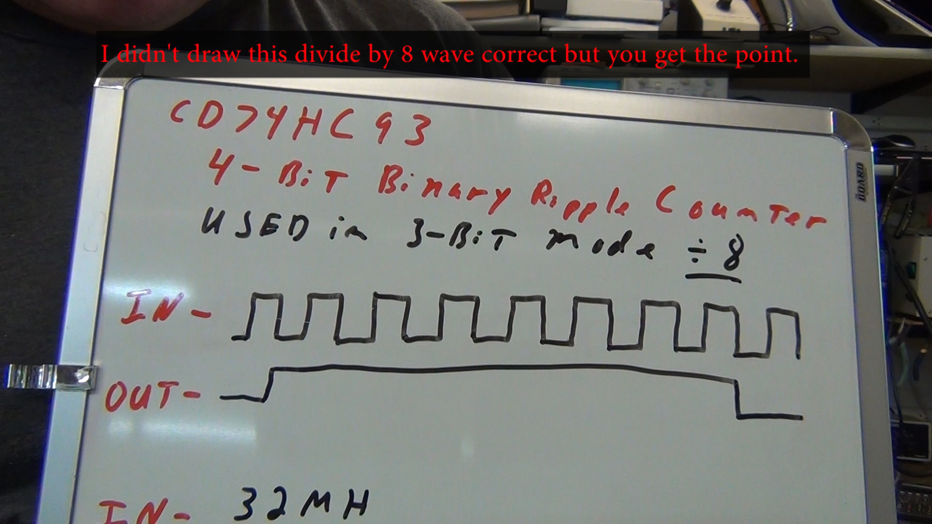
CD74HCT93
Used in 3 bit binary ripple counter mode for divide by 8 with input at CP1 and output at Q3
http://www.ti.com/lit/ds/symlink/cd74hc93.pdf
CD74HC153
Dual 4 to 1 Line Selector/Multiplexer
http://www.ti.com/lit/ds/symlink/cd74hc153.pdf
Here are some photos of what I covered in part one. CLICK ON PHOTO for hi-resolution image.
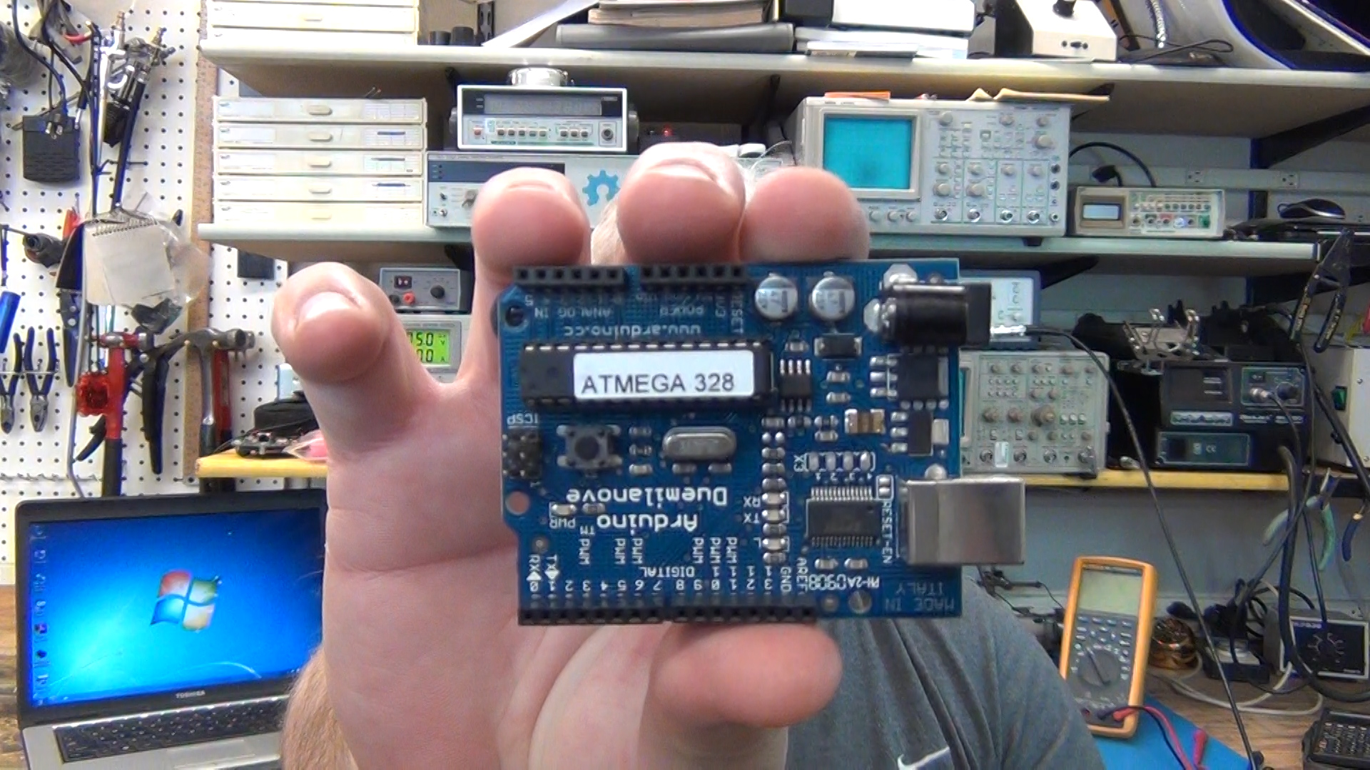
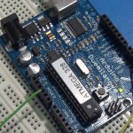
My Arduino I will be using to count freq and do some line select inputs and math.
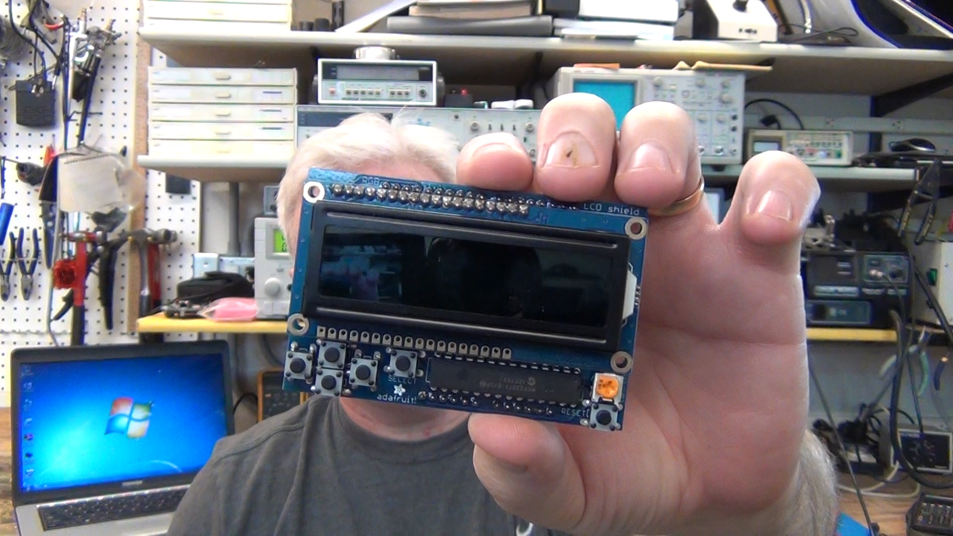
RGB back light dispaly by Adafruit.com for my freq display
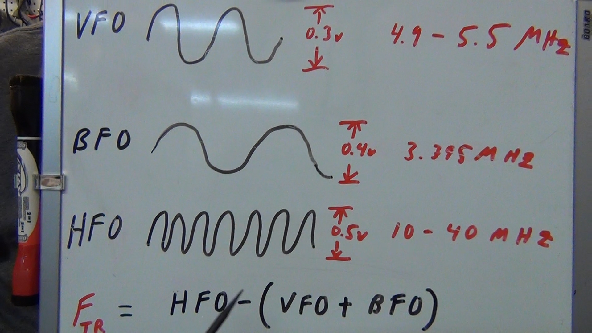
These are the freq I measured coming out of the three RCA jacks on the back of the TS-520S ham radio. I need to count these freq and do some math to know the freq the radio is using.
I can measure the VFO and BFO with the Arduino directly but not the HFO. I will need to use a prescaler to divide the HFO by 8 before it gets to the Arduino.

The library I’m using is coded to use just the one input so my plan is to use a line select chip to multiplex the three signals to this single Arduino input.
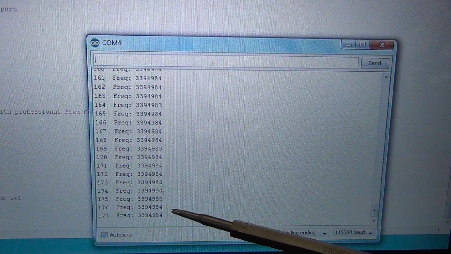
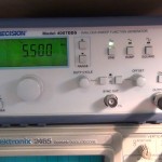
For a test of the Arduino measuring the BFO freq level directly I just created a nice clean 0-5v square wave at 3.395MHz on my freq generator and put it into the input pin the Arduino is coded to use per the library. As you can see it can count this just fine.
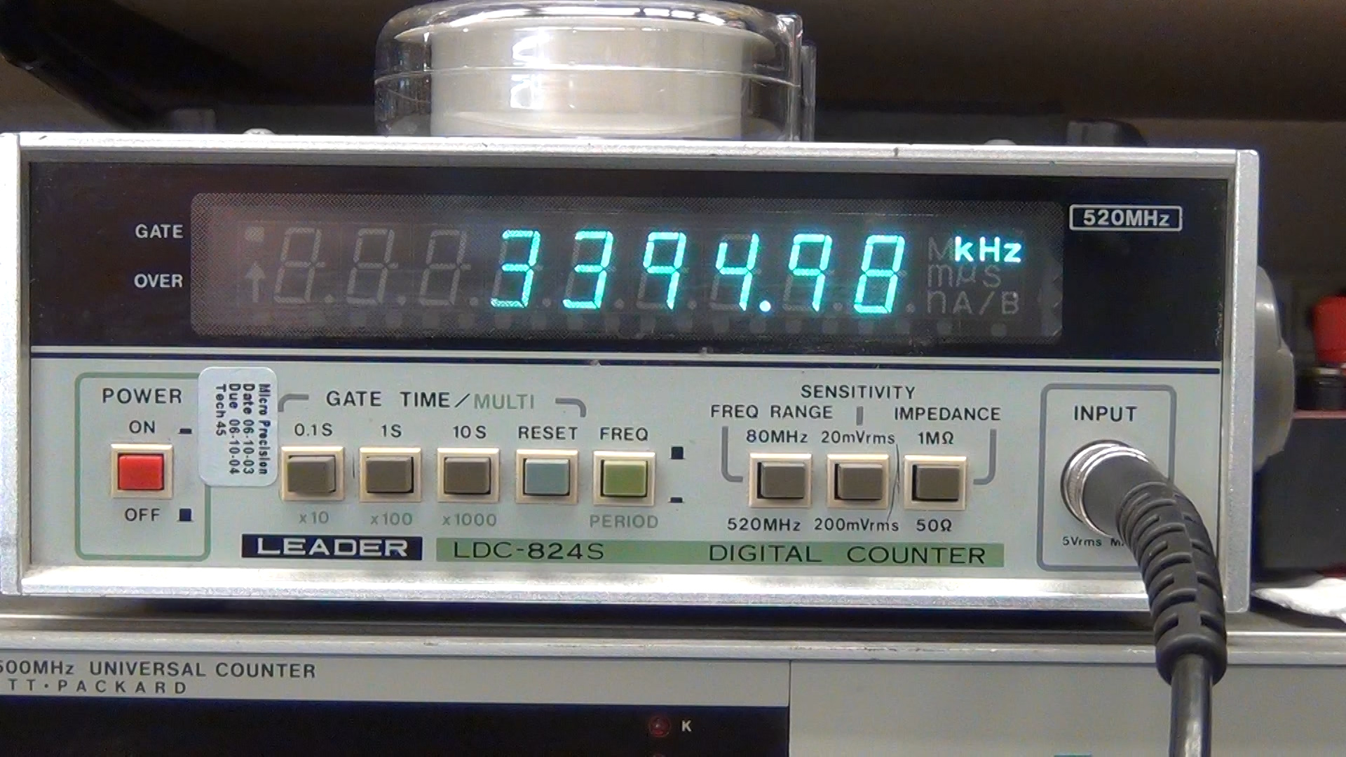
I use my leader to validate the Arduino is correct.
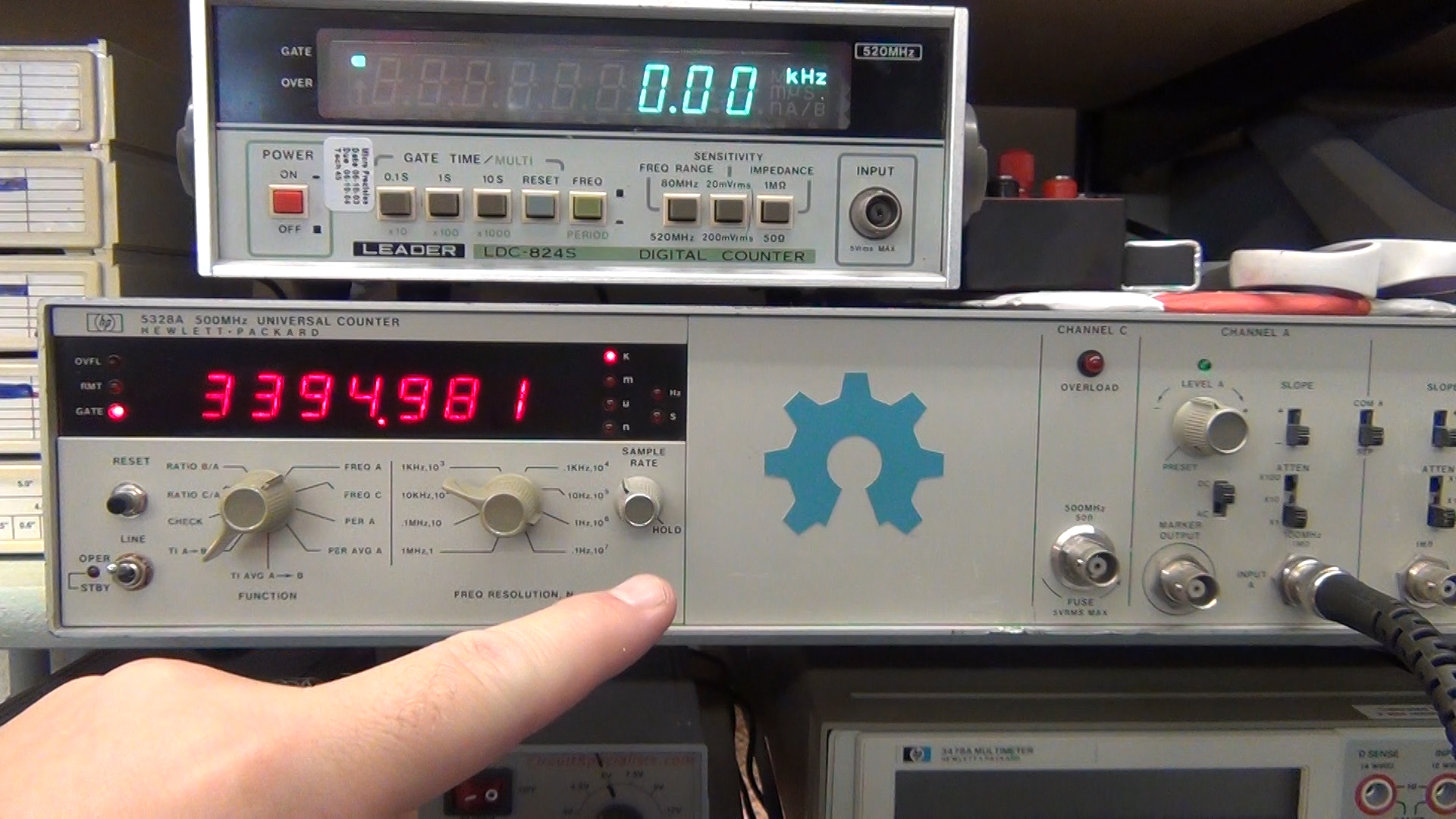
I then double check the Leader and Arduino with my HP counter. All instruments agree to within 1Hz. WOW. Nice.
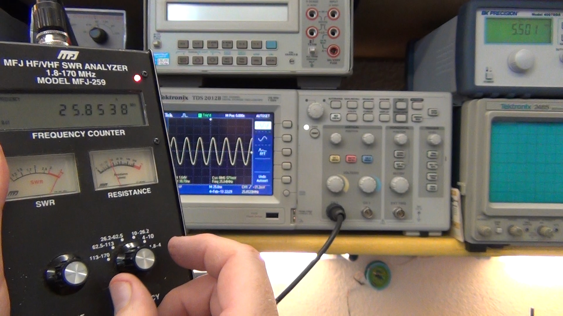
For the HFO I have to use a MFJ-259 SWR antenna analyzer to generate the higher 10 to 40 MHz signal for testing the Arduino.
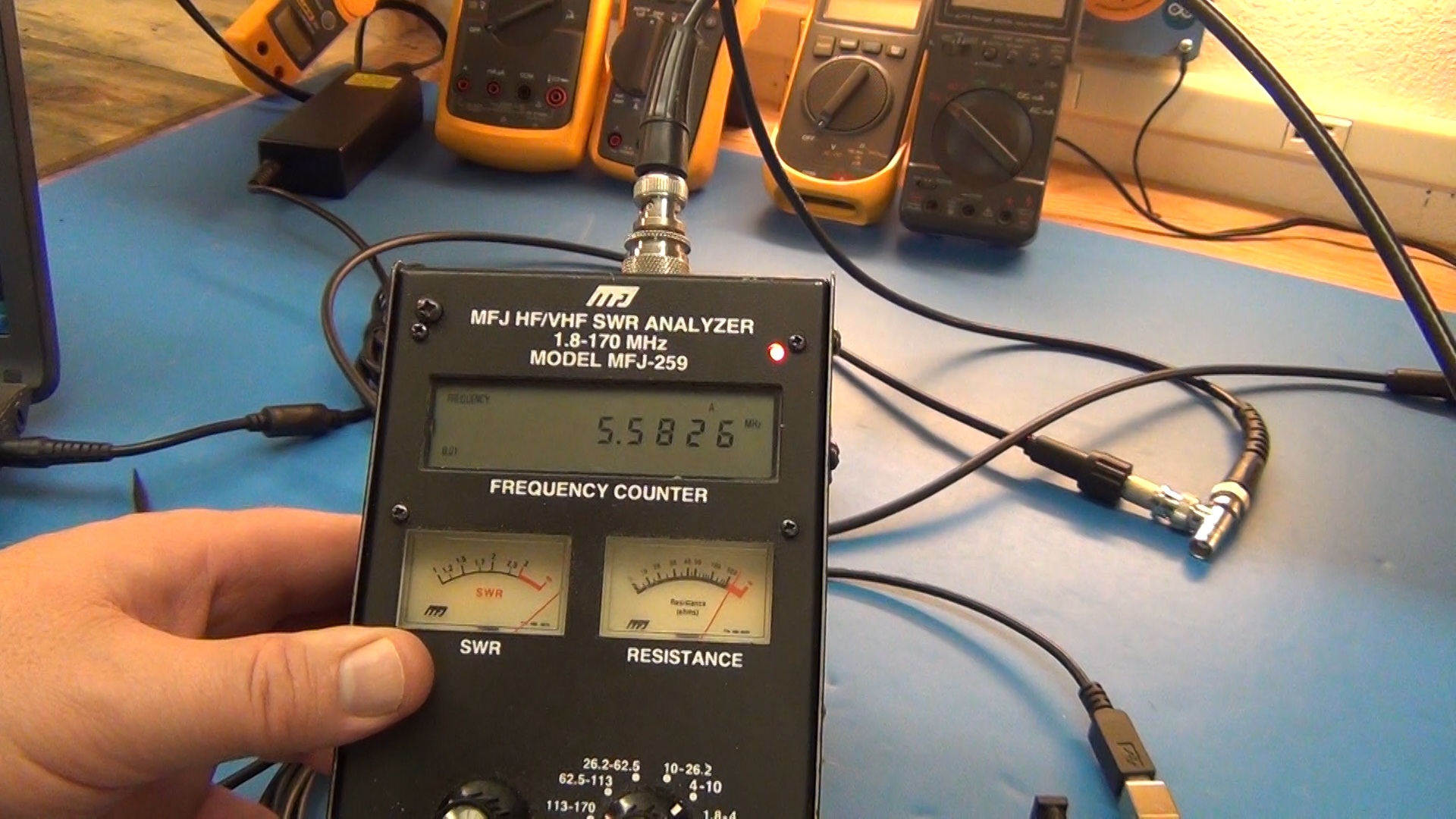
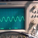
However this instrument only outputs a 1 to 1.1V peak wave which is too low of a voltage level for the Arduino to count.
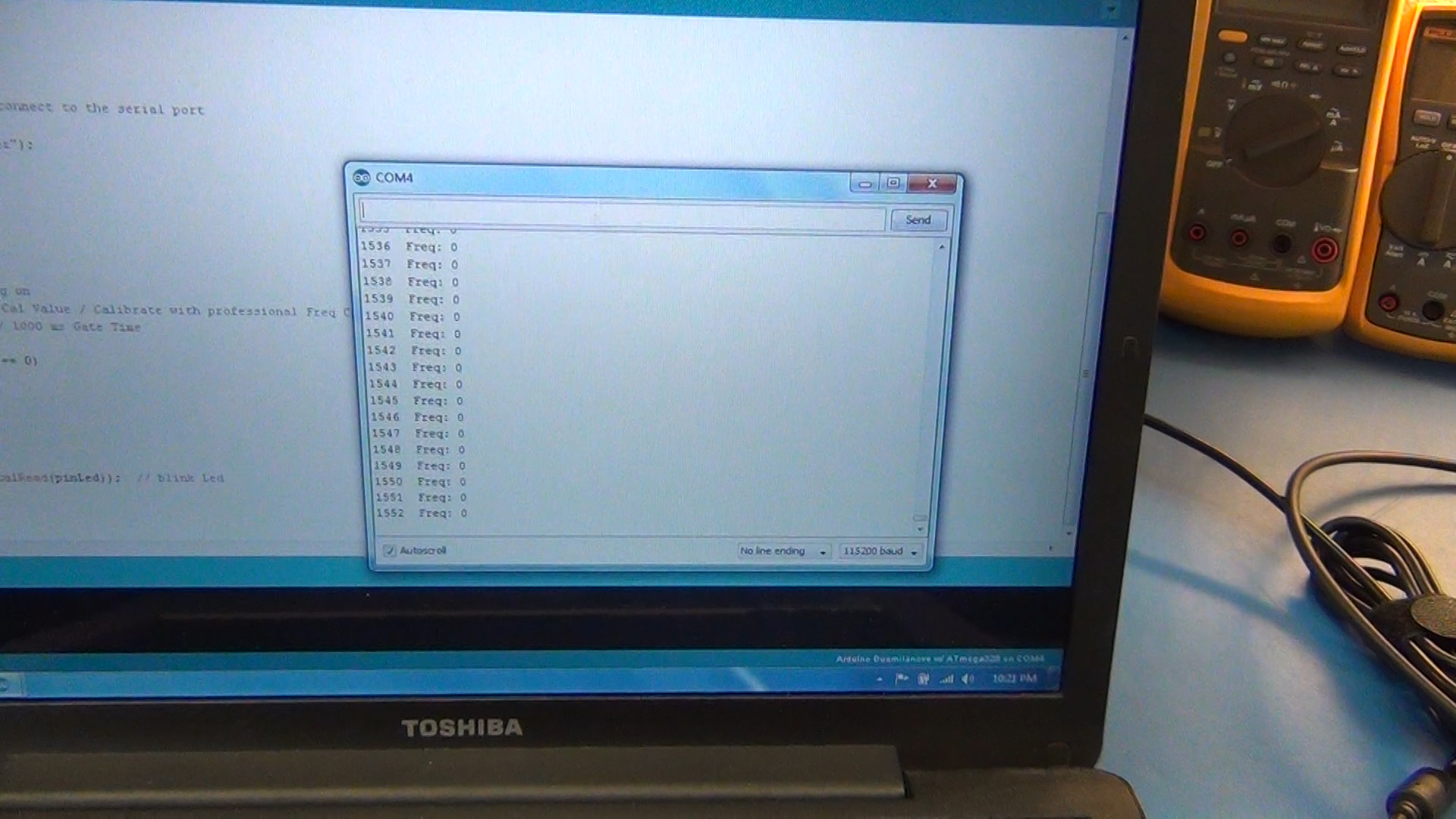
Even at the 5MHz level the Arduino only outputs 0 back to the serial monitor on the PC. It could measure the 5MHz but not at the low voltage levels. I will need to build an amplifier before the Arduino can use the SWR antenna analyzer output for testing.
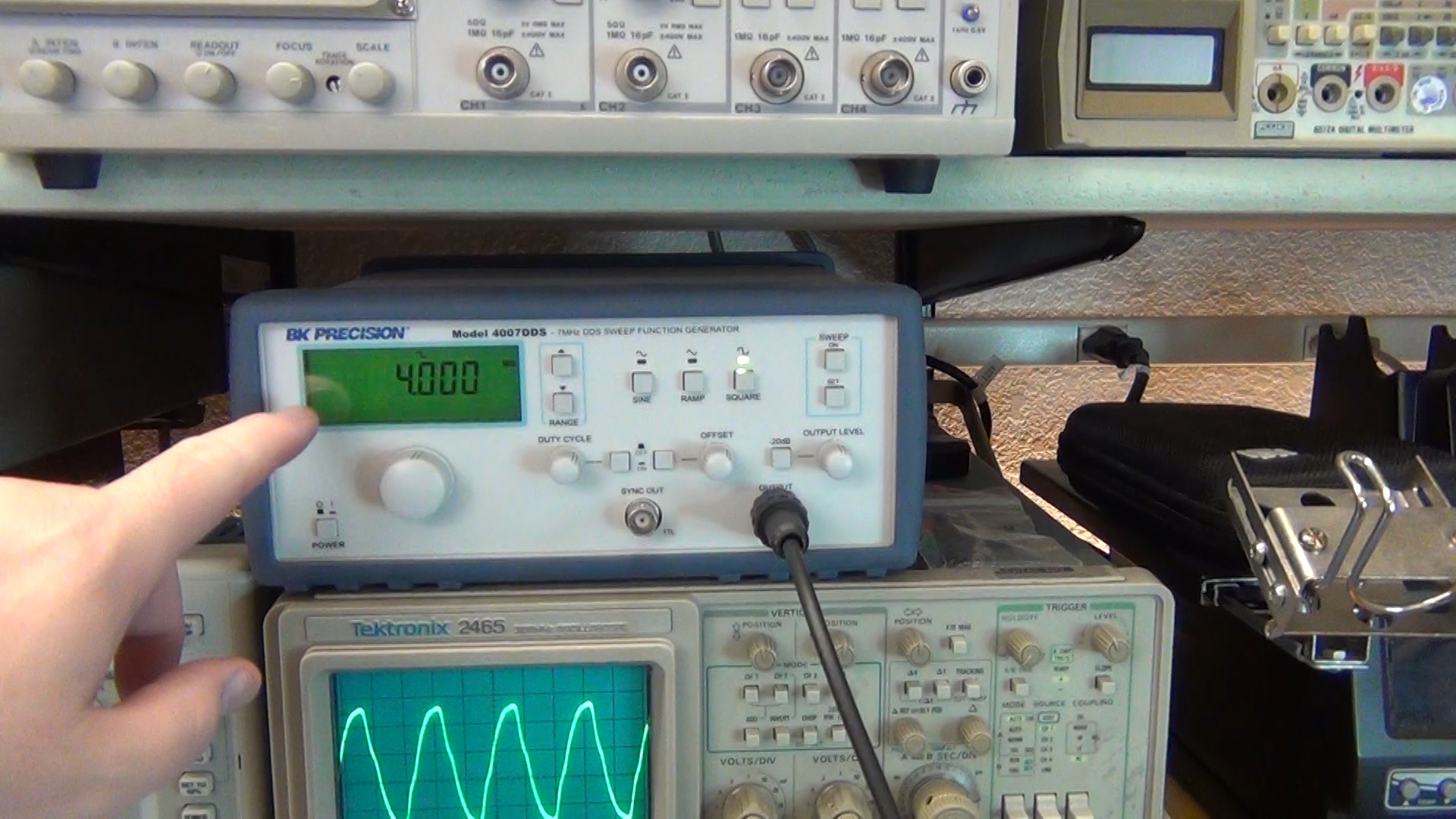
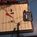
On to testing the divide by 8 prescaler. I output a 4MHz square wave 0-5 v from my function generator.
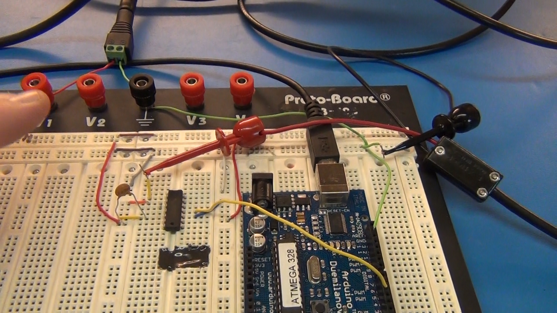
I then pipe this 4MHz into the 4 bit binary ripple counter in 3 bit mode. It should output a clean divide by 8 signal at 500KHz
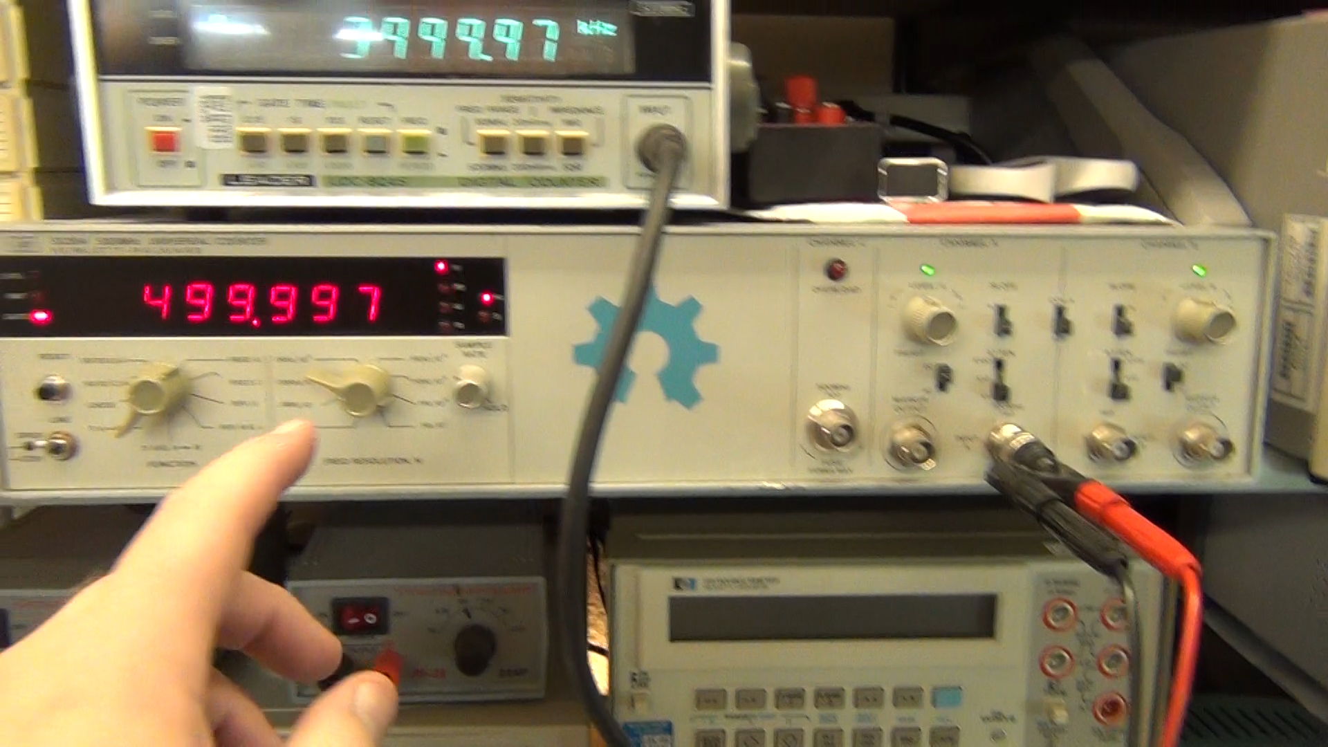
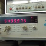
My Leader records the 4MHz in and the HP records the 500KHz out of the chip so we can compare to the Arduino freq count output.
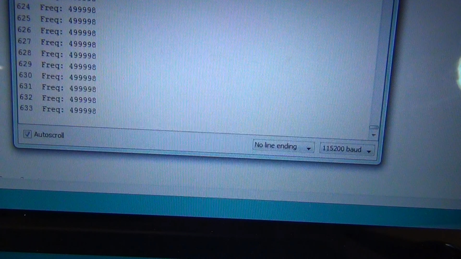
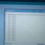
The Arduino reads spot on with the HP at 499,997Hz

This just shows that the Arduino can then do some math to multiply what it counted back to 4MHz with (frq*8) code.

This shows the Leader which is counting the source at 4Mhz agrees with the Arduino’s math to within +/-4Hz. NICE! I only need to be within 100Hz in the end for this to work as a ham radio freq display
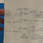
That is it for part one. Part two will start with signal amplification then multiplexing and more. I’m not sure how many parts this will end up being but it is fun to share and I hope fun to follow along.
I have a custom Arduino board project to share including bonus steps at the end on how to program a blank ATmega168 or ATmega328 with your Arduino sketch directly from the Arduino IDE environment using an USBTinyISP programmer from Adafruit.

I’m going to hack a Christmas photo frame I got a few years back when my son visited Santa Clause. The photo of him sitting on Santa’s knee came with a nice frame that had 5 LEDs that flashed when you turned it on. It ran on two AAs and used a “chip-on-board” to control the flashing pattern of the LEDs.
The problem was that this thing flashed all 5 LEDs four times a second! We could never leave it on because it would drive you nuts. Ever since I purchased it I have wanted to hack it so the lighting was not so annoying. This is going to be mostly a video posting but I will put in some “how to” notes, helpful links, photos, circuit and code so it will be more useful to you for adding such a hack to a project of your own.
Below is a video of me describing the problem and proposing the project. A few things did change after the video but I will note the changes below.
Below is the original board from the photo frame. The “chip-on-board” is under the black blob.
READ —>: (more…)


Links for Beginners in Electronics }:-)
Archives
- April 2017 (1)
- March 2017 (3)
- December 2016 (1)
- November 2016 (3)
- October 2016 (2)
- September 2016 (2)
- August 2016 (4)
- June 2016 (1)
- May 2016 (6)
- April 2016 (1)
- March 2016 (3)
- February 2016 (4)
- January 2016 (3)
- December 2015 (1)
- November 2015 (5)
- September 2015 (1)
- July 2015 (2)
- June 2015 (6)
- March 2015 (1)
- January 2015 (2)
- December 2014 (2)
- November 2014 (4)
- October 2014 (2)
- May 2014 (1)
- March 2014 (5)
- February 2014 (3)
- January 2014 (1)
- September 2013 (2)
- August 2013 (1)
- July 2013 (4)
- June 2013 (3)
- May 2013 (2)
- April 2013 (1)
- March 2013 (3)
- February 2013 (2)
- January 2013 (2)
- December 2012 (1)
- November 2012 (8)
- October 2012 (5)
- September 2012 (1)
- August 2012 (1)
- July 2012 (2)
- May 2012 (2)
- April 2012 (1)
- March 2012 (3)
- February 2012 (2)
- December 2011 (2)
- November 2011 (4)
- October 2011 (1)
- September 2011 (1)
- August 2011 (2)
- May 2011 (2)
- April 2011 (2)
- March 2011 (2)
- February 2011 (2)
- January 2011 (1)
- December 2010 (2)
- November 2010 (2)
- July 2010 (3)
- June 2010 (2)
- April 2010 (1)
- March 2010 (1)
- February 2010 (2)
- January 2010 (1)
- December 2009 (2)
- October 2009 (4)
- March 2009 (1)
- December 2008 (1)
- November 2008 (1)
- August 2008 (1)
- April 2008 (1)
- March 2008 (1)
- February 2008 (1)
- June 2007 (1)
- November 2005 (1)
- April 2005 (1)