
This is Part 3. You may want to read (part1) & (part2) first.
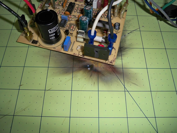
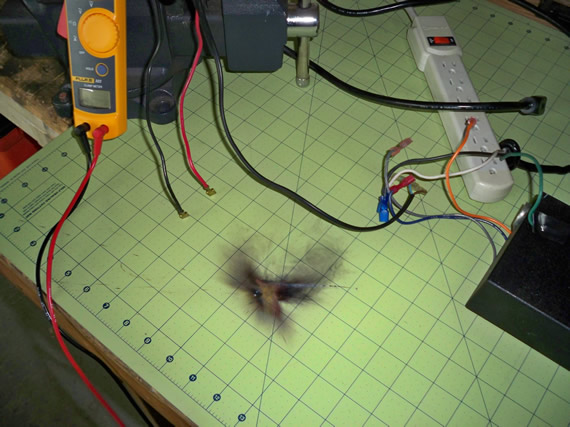
In this part I was going to probe the board to find where the signal was being lost for the controls. After mapping out all the connections and looking up the functionality of the ICs in the earlier postings I was confident I was going to track down the problem. I had the motor secured in my bench vise, the power supply and speed control board connected to the speed sensor feedback and mains 120v to a switch. When I turned on the 120v mains power I could smell something getting hot real fast. I had to work 30 second at a time and let the control board cool between tests. Something was not happy in the power supply! The heat was coming from a large 4watt 1.8K ohm resistor. I didn’t dare probe for more than 30 seconds because it was clearly getting too hot. But I pushed my luck too far (KA-BAM!).
READ —>: (more…)
I was helping HeatSync Labs with their amateur high altitude balloon launch back on August 27th 2010. I finally got time to post the photos and the video. It was a great launch and recovery.
We launched the balloon at 8:04am and recovered it at 10:18am. Here is a link to the GPS tracking data from the balloon.
This flight tracking data may not be available, sorry.
Everything survived the landing. We landed in some farmland just off a dirt road and the transmitter worked the whole time so it was an easy recovery.
READ —>: (more…)
I have a custom Arduino board project to share including bonus steps at the end on how to program a blank ATmega168 or ATmega328 with your Arduino sketch directly from the Arduino IDE environment using an USBTinyISP programmer from Adafruit.

I’m going to hack a Christmas photo frame I got a few years back when my son visited Santa Clause. The photo of him sitting on Santa’s knee came with a nice frame that had 5 LEDs that flashed when you turned it on. It ran on two AAs and used a “chip-on-board” to control the flashing pattern of the LEDs.
The problem was that this thing flashed all 5 LEDs four times a second! We could never leave it on because it would drive you nuts. Ever since I purchased it I have wanted to hack it so the lighting was not so annoying. This is going to be mostly a video posting but I will put in some “how to” notes, helpful links, photos, circuit and code so it will be more useful to you for adding such a hack to a project of your own.
Below is a video of me describing the problem and proposing the project. A few things did change after the video but I will note the changes below.
Below is the original board from the photo frame. The “chip-on-board” is under the black blob.
READ —>: (more…)


Links for Beginners in Electronics }:-)
Archives
- April 2017 (1)
- March 2017 (3)
- December 2016 (1)
- November 2016 (3)
- October 2016 (2)
- September 2016 (2)
- August 2016 (4)
- June 2016 (1)
- May 2016 (6)
- April 2016 (1)
- March 2016 (3)
- February 2016 (4)
- January 2016 (3)
- December 2015 (1)
- November 2015 (5)
- September 2015 (1)
- July 2015 (2)
- June 2015 (6)
- March 2015 (1)
- January 2015 (2)
- December 2014 (2)
- November 2014 (4)
- October 2014 (2)
- May 2014 (1)
- March 2014 (5)
- February 2014 (3)
- January 2014 (1)
- September 2013 (2)
- August 2013 (1)
- July 2013 (4)
- June 2013 (3)
- May 2013 (2)
- April 2013 (1)
- March 2013 (3)
- February 2013 (2)
- January 2013 (2)
- December 2012 (1)
- November 2012 (8)
- October 2012 (5)
- September 2012 (1)
- August 2012 (1)
- July 2012 (2)
- May 2012 (2)
- April 2012 (1)
- March 2012 (3)
- February 2012 (2)
- December 2011 (2)
- November 2011 (4)
- October 2011 (1)
- September 2011 (1)
- August 2011 (2)
- May 2011 (2)
- April 2011 (2)
- March 2011 (2)
- February 2011 (2)
- January 2011 (1)
- December 2010 (2)
- November 2010 (2)
- July 2010 (3)
- June 2010 (2)
- April 2010 (1)
- March 2010 (1)
- February 2010 (2)
- January 2010 (1)
- December 2009 (2)
- October 2009 (4)
- March 2009 (1)
- December 2008 (1)
- November 2008 (1)
- August 2008 (1)
- April 2008 (1)
- March 2008 (1)
- February 2008 (1)
- June 2007 (1)
- November 2005 (1)
- April 2005 (1)