
In this video I rip into my 4 day old $700 Yamaha DGX-640 to move the phono jack from the back to the front of the keyboard. So much for my 3 year warranty :( But it had to be done because it was not accessible in the back plus having the wire draped over the keys or roped between your legs was annoying. Another annoying feature was the easel being mounted at the very back of this large keyboard deck. It was so far away we couldn’t make out smaller notes or markings. So at the beginning of the video I show my swing away easel hack that fixed this issue nicely and was quite easy to make. (After the video is a bunch of hi-res photos)
photo gallery
CLICK PHOTO for gallery view and click a SECOND time for hi-resolution image. Click thumbnails on lower right and lower left of gallery to navigate gallery photos.
-

- The easel is to far to read notes.
-

- I welded a T from strap steel and riveted it to the plastic easel.
-

- Then welded a 3 inch tube at 30 degrees to the T.
-

- A bent rod inserts into the tube so the easel can swing out of the way.
-

- This rod also inserts into a 2nd tube welded to C clamps which are clamped to a self behind the keyboard.
-

- Now the easel is at just the right distance and hight.
-

- The easel swings out of the way.
-

- With the esael out of the way you can get to all the controls.
-

- This is the C clamps which clamps to a self behind the keyboard and as the tube welded on it for a pivit point.
-

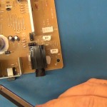
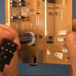
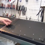
- Now to open up the piano and get to the phono jack.
-
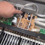
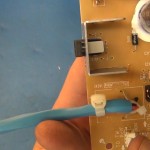
- This is the phono jack I need to move.
-
- The phono jack is going out the back and I need to move it to the front.
-
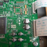
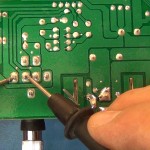
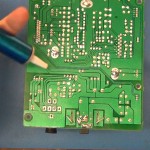
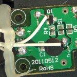
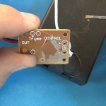
- Control board photo
-

- Control board photo
-
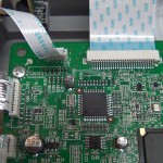
- Control board photo
-

- Control board photo
-
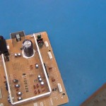
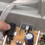
- Power board is out and ready for hacking
-
- If you ever have a power problem with such a keyboard remember there is a fuse on this power board.
-
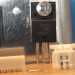
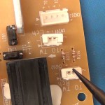
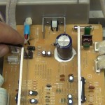
- Close up of the voltage regulators
-
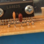
- LA4625 – 2 channel 13.5W BTL audio power amplifier
-
- Speaker connectors on power board.
-
- In the video I demonstrate how the phono plug controls the continuity to the speakers.
-
- I use a solder sucker to remove the phono jack.
-
- Ready to move the jack plug
-
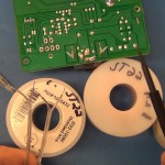
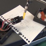
- I picked large wire for the internal speakers and ground and small 22 AWG stranded wire for the headset wires.
-
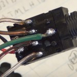
- Solder these select wires to the power board
-
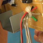
- Shrink wrap and wire tie for strain relief
-
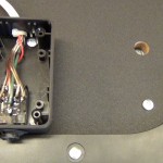
- Power board is back in the piano and phono wires are going out the back.
-
- These wires just need to go to the new location for the external jack
-

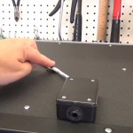
- I used a simple Radio Shack project box for the enclosure.
-
- Solded the relocation wires to the photo jack
-
- Screwed it to the bottom of the MDF board.
-

- Some extra shrink wrap and close up the box.
-
- Some sticky tab cable hold downs to keep the wires up and out of the way.
-

- Testing for the firs time.
-

- Sounds good to me but nobody else in the house will be bothered now.
-

- All good and thanks for joining.
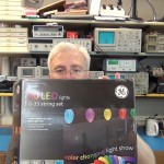
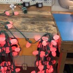
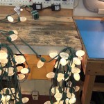
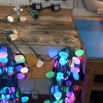
I wanted to synchronize my GE G-35 multi pattern Christmas lights this year.
I did a full tear down last year of these lights and you can see that (here)
My biggest problem, aside from hating the 14 patterns GE forces on these lights, is that you can’t chain or synchronize multiple strings. So in my case I have two strings starting from a peak with one going left and the other going right. They say in the instructions you can synchronize two sets by setting the same pattern and then turning them both on at the same time. However within 30 minutes the patterns are no longer in sync on the two sides of my roof and that looks horrible.
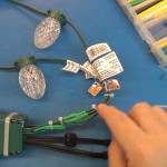
This is a posting showing how I hacked two strings to use one controller and it is working great. The two strings can never be out of sync, COOL! I know others have done the same so I know this is a sold hack for up to 3 strings in parallel using one control box.
Of course others have gone much farther controlling these lights making their own control boards and adding network connection. I will link to them at the bottom of this posting
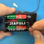
Instructions:
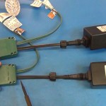
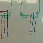
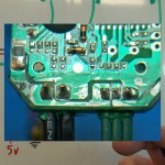
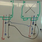
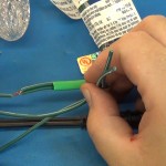
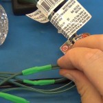
To do this hack you cut the ground and data lines going to the bulbs on both sets (don’t cut any power wires which have the faint white printing, see photo). Then terminate one data line coming out of one controller by sealing it in heat shrink. The data line is the middle wire to the lights.
Tie and solder the data line from the 2nd controller to both data lines going to the lights. Then tie and solder ALL 4 of the grounds together so that the circuits have a common ground. The ground is the right side wire when looking at the screw side of the controller box. The ground will be the wire that does not have any faint white lettering on it. Seal everything up with heat shrink.
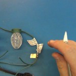
You still have to plug in all the transformers because the lights need all the power. That’s it and now your parallel strings will always be 100% in sync.
Enjoy the video and let me know if you try this hack and how it works out.
photo gallery
CLICK PHOTO for gallery view and click a SECOND time for hi-resolution image. Click thumbnails on low right and lower left of gallery to navigate gallery photos.


If you want to go down the rabbit hole more than I did I will keep some updated links below as I find them.
DigitalMisery.com has an open source drop in wireless replace board for these lights. WOW, you can’t ask for more than that. He does not sell the boards yet but keep checking his site to see if he gets a Kick starter going or just follow his open source documents and spin your own board. He links to his code and the Arduino library’s “G35Arduino”
DeepDarc.com put up some amazing engineering details on these lights and reverse engineered both the radio protocol and the protocol used on the LED data bus. You must read his post if you’re going to be hacking these lights. He also shares his code and other very useful tips.
Keithsw has some great stuff synchronizing 6 strands and shares his control code, Arduino circuit and a PC software simulator program to help design the layout and patterns. Here is his short (video).
CheerLights is an ioBridge Labs project that allows people all across the world to synchronize their lights. This sit gives all the hacking details and you can play along even it you don’t have lights by tweeting a color to @cheerlights and watching on ustream.
Jim at Jim’s G-35 Project Page makes his own control board using a PIC18F2620 micro controler.
If I have any of my own hack updates I will link to them from here and under “All Postings” with the title “G35 LED Christmas Light…”
UPDATE 11/11/2012 for EXTRA LINKS:
Good arduino example with new library – (digitalmisery.com)
11/21/2011: Added new Arduino IDE 1.0.1 supported code – (digitalmisery.com)
(github.com/MarkEMarkEMark/G35-MEO-Programs)
UPDATE 12/18/2012 for EXTRA LINKS:
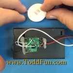
Not much here. Just a quick teardown and fly-over of the “Try Me” button and circuit that was used in the packaging of the first LED Christmas light review “Symphony of Lights Style C9 Bulbs“.
Link: Intro review blog posting on this 3 review set
Thanks for joining and remember to subscribe to my YouTube channel and my ToddFun.com RSS feed.
photo gallery
CLICK PHOTO for gallery view and click a SECOND time for hi-resolution image. Click thumbnails on low right and lower left of gallery to navigate gallery photos.


Links for Beginners in Electronics }:-)
Archives
- April 2017 (1)
- March 2017 (3)
- December 2016 (1)
- November 2016 (3)
- October 2016 (2)
- September 2016 (2)
- August 2016 (4)
- June 2016 (1)
- May 2016 (6)
- April 2016 (1)
- March 2016 (3)
- February 2016 (4)
- January 2016 (3)
- December 2015 (1)
- November 2015 (5)
- September 2015 (1)
- July 2015 (2)
- June 2015 (6)
- March 2015 (1)
- January 2015 (2)
- December 2014 (2)
- November 2014 (4)
- October 2014 (2)
- May 2014 (1)
- March 2014 (5)
- February 2014 (3)
- January 2014 (1)
- September 2013 (2)
- August 2013 (1)
- July 2013 (4)
- June 2013 (3)
- May 2013 (2)
- April 2013 (1)
- March 2013 (3)
- February 2013 (2)
- January 2013 (2)
- December 2012 (1)
- November 2012 (8)
- October 2012 (5)
- September 2012 (1)
- August 2012 (1)
- July 2012 (2)
- May 2012 (2)
- April 2012 (1)
- March 2012 (3)
- February 2012 (2)
- December 2011 (2)
- November 2011 (4)
- October 2011 (1)
- September 2011 (1)
- August 2011 (2)
- May 2011 (2)
- April 2011 (2)
- March 2011 (2)
- February 2011 (2)
- January 2011 (1)
- December 2010 (2)
- November 2010 (2)
- July 2010 (3)
- June 2010 (2)
- April 2010 (1)
- March 2010 (1)
- February 2010 (2)
- January 2010 (1)
- December 2009 (2)
- October 2009 (4)
- March 2009 (1)
- December 2008 (1)
- November 2008 (1)
- August 2008 (1)
- April 2008 (1)
- March 2008 (1)
- February 2008 (1)
- June 2007 (1)
- November 2005 (1)
- April 2005 (1)